Manual for Indoor Micro LoRaWAN Gateway - GWIML
.png)
Thank you very much for choosing Daviteq Wireless Sensors and Gateways. We are the leading wireless sensor manufacturer in the World. We have a wide range of wireless sensors and gateway which support different connectivity like LoRaWAN, Sigfox, Sub-GHz, NB-IoT...Please find out more information at this link.
This manual is applied to the following products
| Item code | HW Version | Firmware Version | Remarks |
| GWIML-8-WF-ETH-01 | 1.0 | 1.0 |
To use this product, please refer step by step to the below instructions.
1. Quick Guide
Reading time: 10 minutes
Finish this part so you can understand and put the sensor in operation with the default configuration from the factory.
1.1 What is the GWIML ?
GWIML is a Micro LoRaWAN Gateway designed for indoor installation, suitable for small businesses or private area use cases like parking spaces, exhibition centers or campuses, etc. It is also suitable for providing coverage for indoor blind spots. It supports simultaneously 8 connection channels to help receive a large number of packets from surrounding LoRaWAN sensors. It supports host common communications, Ethernet or WiFi. For LoraWAN communication, it supports LoRa frequency 863~870 MHz / 902~928 MHz.
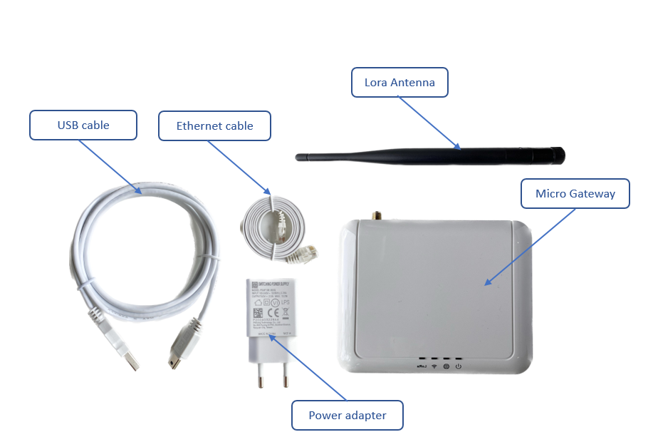
1.2 What's in the package?
The package includes:
01 x Micro LoraWAN Gateway
01 x Lora Antenna
01 x Power adapter (USB Charger 100-240VAC 50/60Hz to 5VDC/2A)
01 x USB cable 1.5 meters for charging purpose
01 x Ethernet cable
1.3 Product Overview
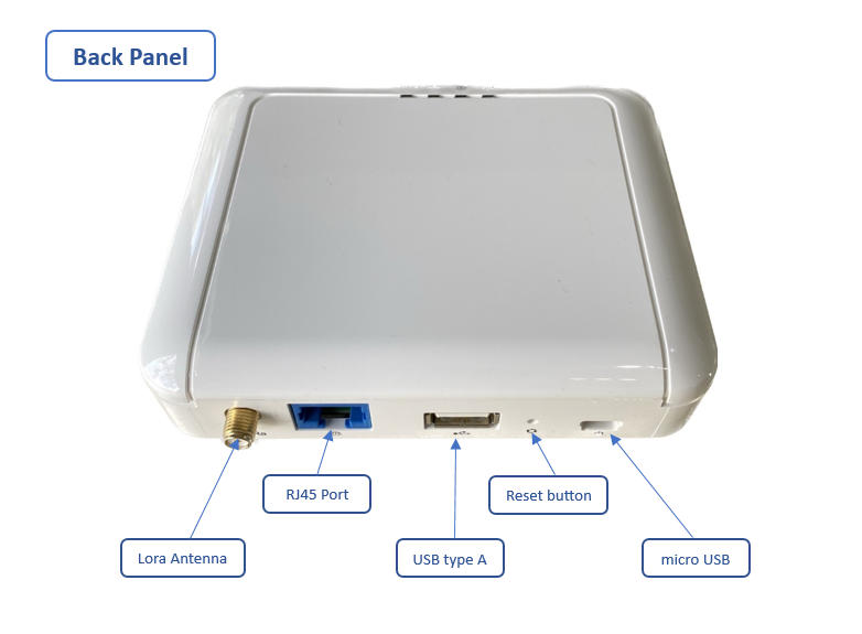
1.3.1 I/O Ports
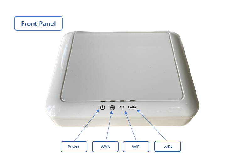
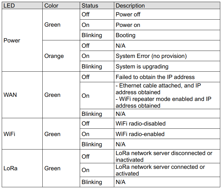
1.3.2 LED Functions
1.3.3 Reset Button
Only use for troubleshooting
1.4 Installation
Startup the LoraWAN Gateway through the following steps
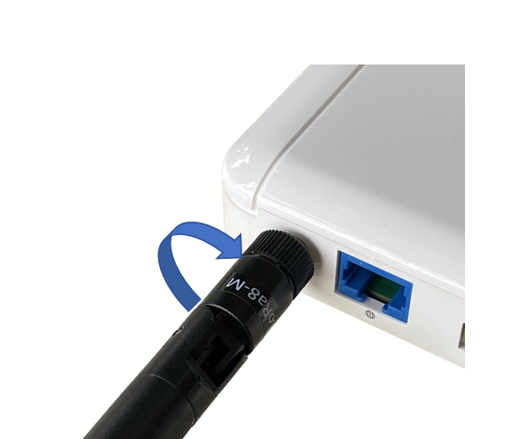
Step 1: Install the antennas of the LoRaWAN Gateway
Install the antenna in the correct position. Make sure the antenna and Gateway are tightly connected.
Step 2: Connect the Ethernet cable and power up the Gateway
Connect the Ethernet cable into RJ45 port of the gateway and the port of Ethernet network. After that, connect the power adapter provided to the Micro USB port. The gateway will automatically turn on after powering up.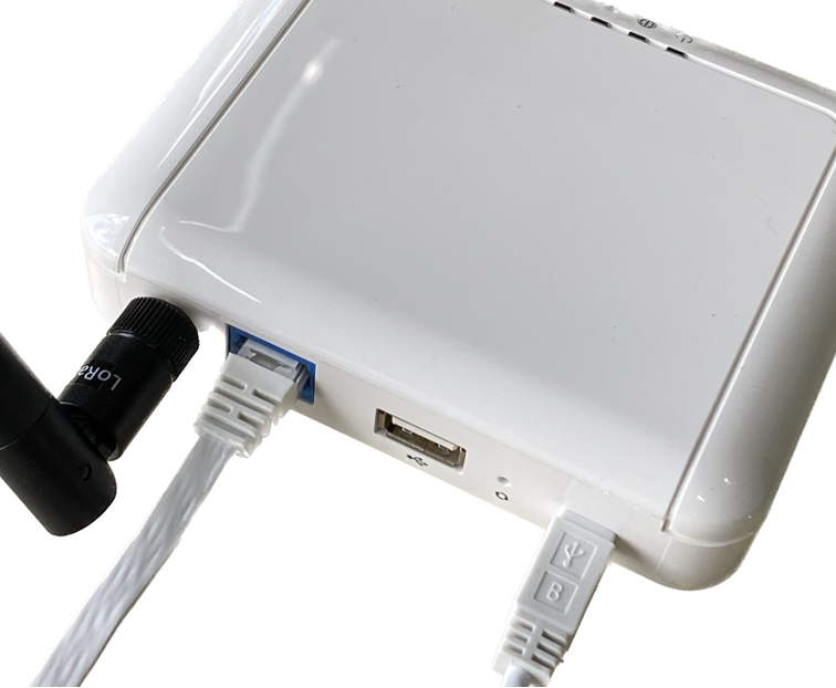
Note: If the gateway use WiFi mode connect to Network Sever, Skip connect the Ethernet cable
1.5 Configure the LoRaWAN Gateway
1.5.1 GUI Access
Once gateway is turned on through plugging in the adapter, it will become a local wifi access point.
To access the GUI, follow these steps:
Step 1:Connect to Micro Gateway via local wifi (SSID: on the gateway label).
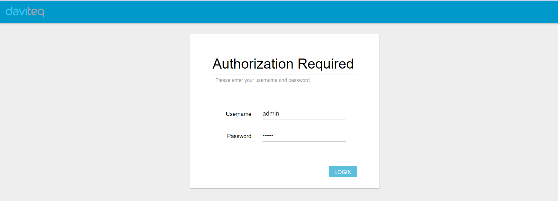
Step 2: Enter the default IP address (192.168.55.1) of the gateway in the web browser to access the configuration interface.
The default username is “admin” and the password is "admin“.
1.5.2 WAN configuration
The purpose of this category is to view current WAN settings. This category is further divided into three sub- sectors: WAN Status, Ethernet Wan and Wireless Extender. These individual options are lodged and labeled above the main content panel.
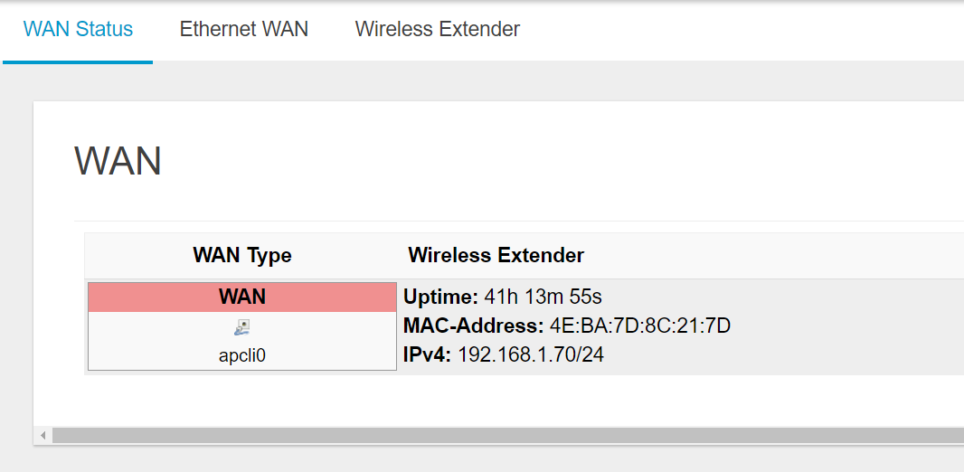
- WAN Status
The current network status will be shown on this page.
- Ethernet WAN
This page is to set up the connection type in terms of Static IP, DHCP client, or PPPoE. The three different options can be selected in the drop-down menu in “wantype”. Please fill in the respective fields exhibited under each selection.
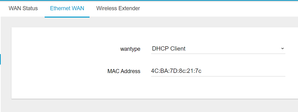
Please make sure the Ethernet cable is connected to a WAN port.
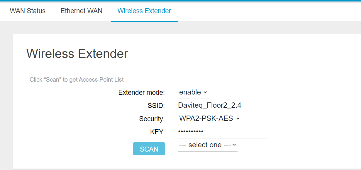
- Wireless Extender
This page is to set up the Wireless Extender Mode for the WAN connection. To activate the extended wireless connection, please select “enable” from the Extender mode drop-down menu. Click the “SCAN” button to obtain the list of available Access Points within your surrounding vicinity.
1.5.3 Lora Settings (Packet Forward)
- Sever Settings
Select Packet Forwarder in the left menu, then choose Setting. After that, select Gateway Infor tab. This page is for setting up the LoRa configuration including Gateway ID, Server Address, Server Uplink Port, Server Downlink Port, Keep-Alive Interval, Statistics Display Interval, and Push Timeout.
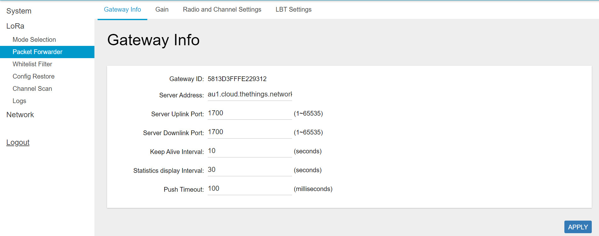
Need to properly configure the Server Address, Server Uplink Port, and Server Downlink Port fields. These information depend on the Network server.
Get the Gateway ID to register the device on Network Server in this step.
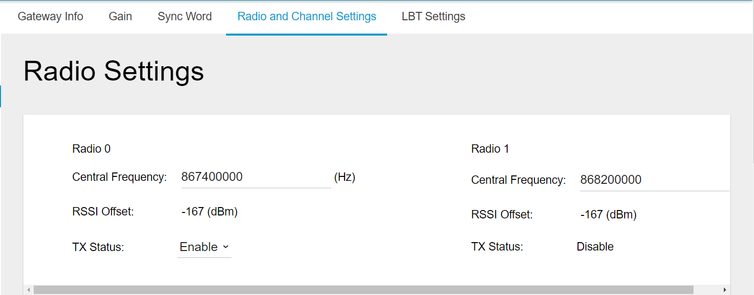
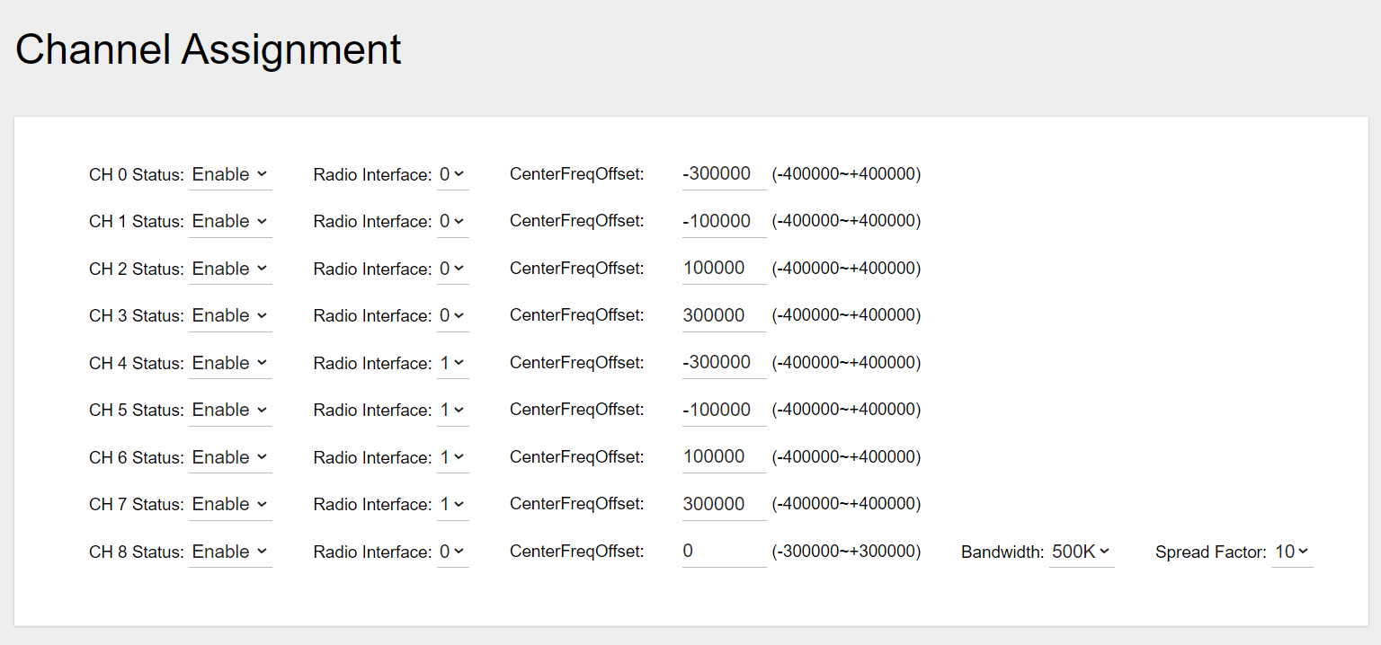
- Radio and Channel Settings
This page is for configuring the radio 0 and radio 1 configurations of Lora, including Central Frequency, Channel Status, and Center frequency offset. The frequencies and channels are regulated by the lora-alliance, region and the network server. Below is an example of the configuration of the frequency EU868.
1.6 Add the LoraWAN Gateway to Network Server
To give an example, please follow the instructions in this link to add LoraWAN gateway to The things Stack network server.
2. Product specification
|
LoRaWAN Specification |
LoRaWAN 1.0.3 |
|
Frequency Band |
Select 863~870 MHz / 902~928 MHz |
|
Number of Channels |
Up to 8 concurrent channels for LoRa transmission |
|
LoRa Transmit Power |
0.5W (up to 27 dBm) |
|
LoRa Receive Sensitivity |
Down to -142 dBm (conducted) |
|
LoRa Software |
Standard and LRR Actility |
|
Operating Temperature |
-10°C ~ 55°C |
|
Storage Temperature |
-20°C ~ 60°C |
|
Power Supply |
5VDC/2A via mini-USB port |
|
Wireless LAN |
802.11 b/g/n 2.4G |
|
Interfaces |
LAN 10/100Mbps, 1 USB 2.0 for firmware upgrade, 4 LED indicators |
|
Antenna Type |
Built-in Wi-Fi and LoRa antenna and one (1) external SMA connector for LoRa |
|
Dimensions |
L:116 x W:91 x H:27 mm |
|
Weight |
0.4 kg |
3. Warranty and Support
For warranty terms and support procedures, please refer to this link.
4. References
Use-cases:
Case studies:
White-papers:
END.
No Comments