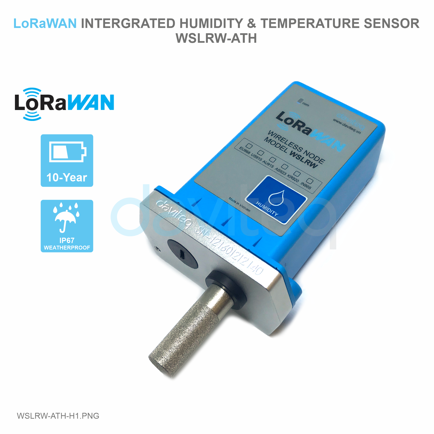
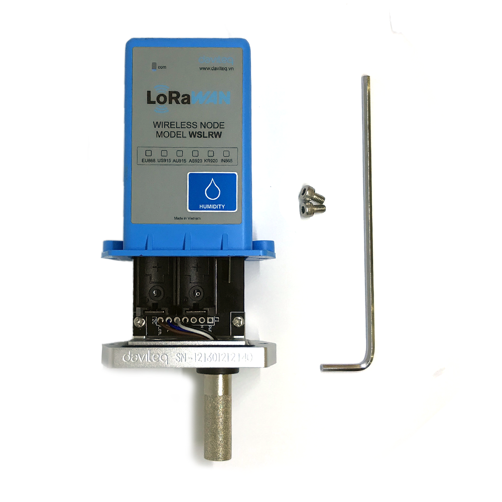
USER GUIDE FOR LORAWAN INTEGRATED HUMIDITY & TEMPERATURE SENSOR WSLRW-ATH
THIS IS OBSOLETE MANUAL
Please access https://www.iot.daviteq.com/wireless-sensors for updated manual
| WSLRW-ATH-MN-EN-01 |
JUL-2020 |
This document is applied for the following products
| SKU | WSLRW-ATH | HW Ver. | 1.2 | FW Ver. | 1.0 |
| Item Code |
WSLRW-ATH-9-10 | Wireless LoRaWAN Integrated Humidity & Temperature Sensor, Internal antenna, Type AA battery 1.5VDC, IP67, 900-930 Mhz | |||
| WSLRW-ATH-8-10 | Wireless LoRaWAN Integrated Humidity & Temperature Sensor, Internal antenna, Type AA battery 1.5VDC, IP67, 860-870 Mhz | ||||
0. Configuration Check List

|
STEP 1: Configure End Device |
Setting value (Example) |
| 1. Select region |
AS923, IN865, EU868,.. (refer to register address 317)
|
| 2. End Device Operation | OTAA or ABP |
|
|
|
|
| 3. Configure "cycle send data" |
900 sec (Defaut)
|
| 4. Configure "sensor sampling_rate" | 120 sec (Defaut) |
| 5. Configure parameters of sensor | (Refer to Check data configuration table) |
|
(Ex: URSALINK Gateway) |
|
|
1. Configure the information in the General tab |
Server address, Server port (For more information) |
|
2. Configure the information in the Radio tab |
Select the Region Region (Other parameters to default) |
|
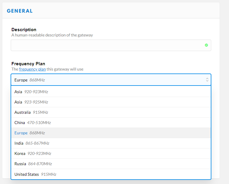
STEP 3: Configure the operation of LoRaWAN Gateway on Network Server |
(Ex: URSALINK Gateway with Thethingsnetwork)
|
| 1. Gateway ID registration | Gateway ID is the GatewayEUI information on the Gateway |
| 2. Frequency Plan parameters configuration |
Asia 920-923MHz, Europe 868MHz,...
|
| 3. Router parameters configuration |
|
| 4. Check the connection of the gateway to the network server |
The Gateway status LED lights up and displays the message "Status: conneted" on the Thethingsnetwork |
|
STEP 4: Configure the operation of Application Server on Network Server |
|
| 1. App ID registration |
|
|
2. Handler parameters configuration |
|
|
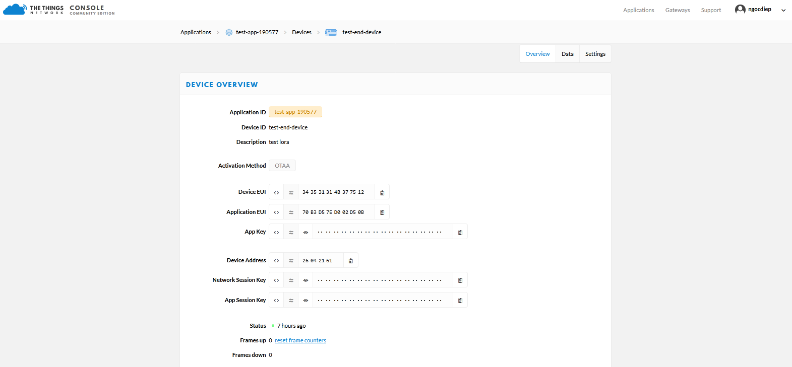
STEP 5: Register Lorawan End Device on Application Server on Thethingsnetwork |
|
|
1. ID Registration |
|
|
2.Select operation mode |
OTAA or ABP |
|
Configure parameters DevEUI and AppKEY |
|
Configure parameters Device Address, Network Session Key, App Session Key |

1. Functions Change Log
| HW Ver. | FW Ver. | Release Date | Functions Change |
|
1.1 |
1.0.0 |
21-July-2020 |
|
|
1.1 |
1.1.x |
05-Oct-2020 |
|
|
1.1 |
1.2.0 |
12-Oct-2020 |
|
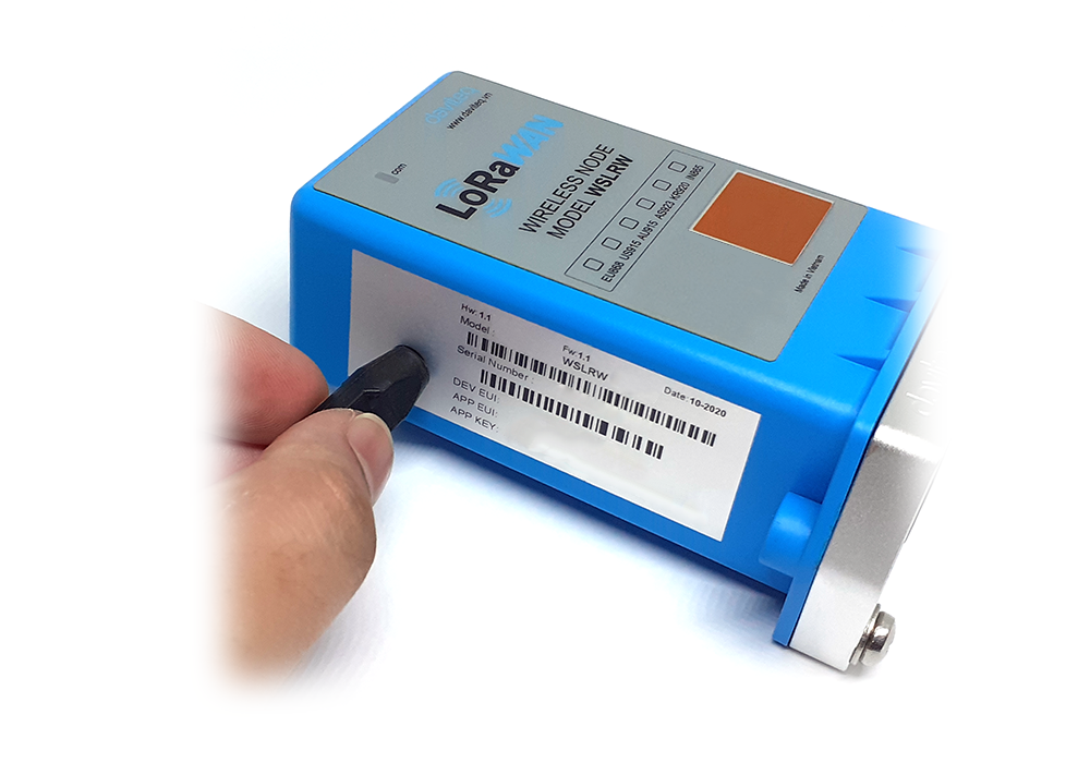
2. Introduction
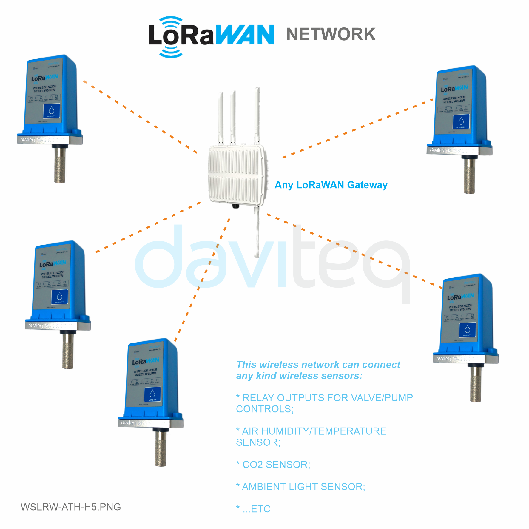
WSLRW-ATH is the LoRaWAN Integrated Ambient Humidity & Temperature Sensor, it utilises Digital capacitance humidity sensor to deliver high accuracy and stable measurement. With Ultra-low power design and smart firmware allow the sensor can last up to 10 years with 2 x AA battery (depends on configuration). The sensor will transmit data in kilo-meters distance to LoRaWAN gateway, any brand on the market. There are a lot of applications as environment monitoring for office, warehouse, data center, hospital, agriculture...
3. Specification
| SENSORS SPECIFICATION: | |
| Sensor | Digital type, factory calibrated, output both Humidity & Temperature values |
| Humidity measuring range & accuracy | 0 .. 100 %RH, +/- 2.0% |
| Humidity resolution | 0.1% |
| Temperature measuring range & accuracy | -40 .. + 85 oC, +/- 0.2 oC |
| Temperature resolution | 0.1 oC |
| Sensor Filter | 20um Alloy sintered filter |
| LoRaWAN SPECIFICATION: | |
| Data rate | 250bps .. 5kbps |
| Antenna | Internal Antenna 2.67 dbi |
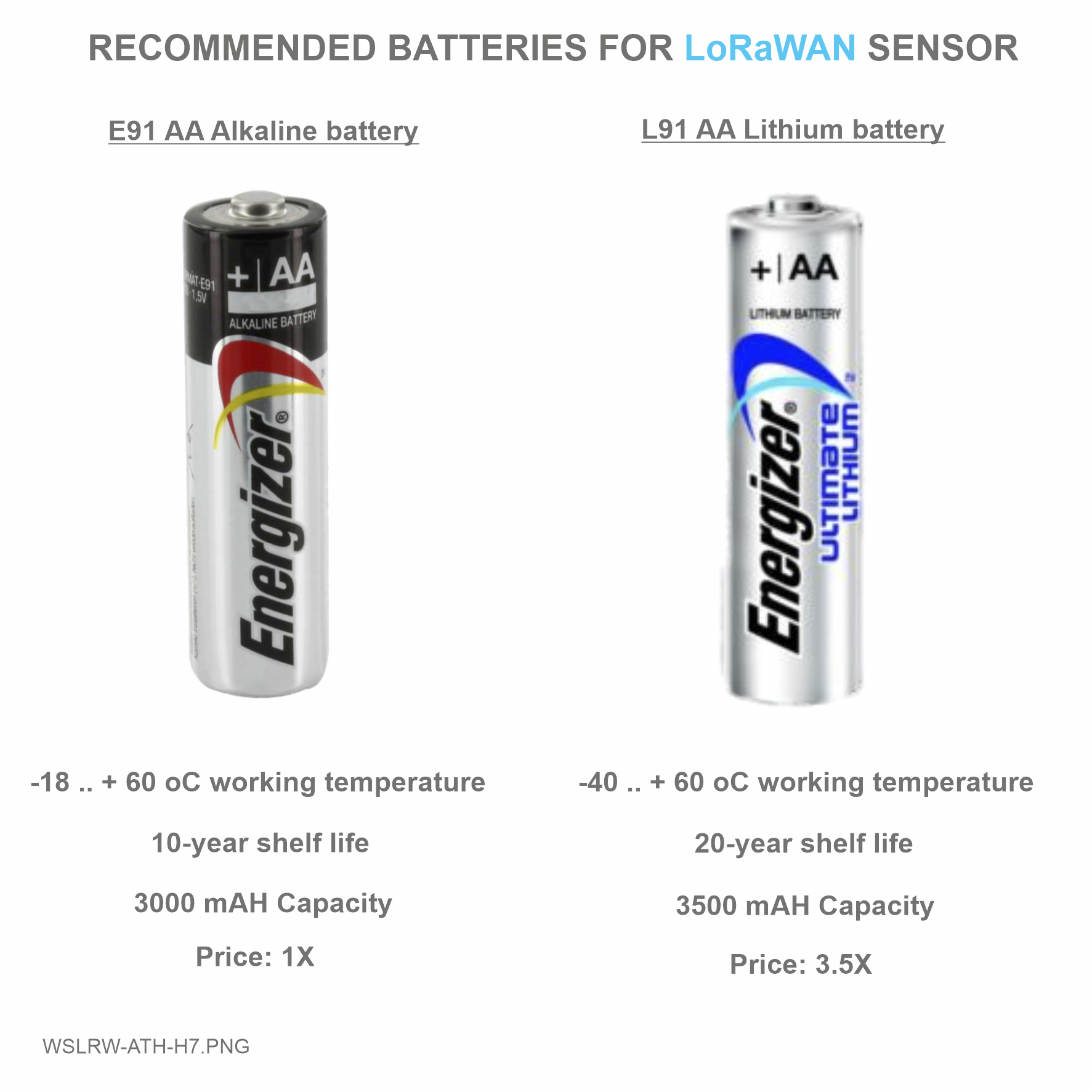
| Battery | 02 x AA 1.5 VDC, working time up to 10 years, battery not included |
| RF Frequency and Power | 860..930Mhz, +14 .. +20 dBm, configurable |
| Protocol | LoRaWAN, class A |
| Data sending modes | Interval time and when alarm occurred |
| RF Module complies to | ETSI EN 300 220, EN 303 204 (Europe) FCC CFR47 Part15 (US), ARIB STD-T108 (Japan) |
| Vietnam Type Approval | |
| Working temperature | -40oC..+60oC (with AA L91 Energizer) |
| Dimensions | H137xW73xD42 |
| Net-weight | 250 grams |
| Housing | Polycarbonate & POM plastic, IP67 |
4. Operation Principle
4.1 LoRaWAN protocol specifications
4.1.1 LoRaWAN Sensor protocol specifications
- LoRaWAN Protocol Version 1.0.3
- Application Server Version 1.3.0.0
- MAC Layer Version 4.4.2.0
- Radio Standards: LoRa Alliance Certified
- LoRaWAN Zone: LoRa Alliance AS923, KR920, AU915, US915, EU868, IN865, RU864
- Class A
- Join Active: OTAA / ABP
- Network Mode: Public Network / Private Network
- Tx Power: upto 20 dBm
- Frequency 860 - 930Mhz
- Date rate 250 bps - 5kbps
- Spreading factor SF12 - SF7
- Bandwidth 125 kHz
- Unconfirmed-data message
-
LoRaWAN application port for certification: 224
4.1.2 Data rate of LoRaWAN Sensor
|
Data rate name |
Data rate (bps) |
Spreading factor (SF) |
Bandwidth (kHz) |
Region |
|
DR2 |
980 |
SF10 |
125 |
AS923, AU915 |
|
DR3 |
1760 |
SF9 |
125 |
|
|
DR4 |
3125 |
SF8 |
125 |
|
|
DR5 |
5470 |
SF7 |
125 |
|
Data rate name |
Data rate (bps) |
Spreading factor (SF) |
Bandwidth (kHz) |
Region |
|
DR0 |
980 |
SF10 |
125 |
US915 |
|
DR1 |
1760 |
SF9 |
125 |
|
|
DR2 |
3125 |
SF8 |
125 |
|
|
DR3 |
5470 |
SF7 |
125 |
|
Data rate name |
Data rate (bps) |
Spreading factor (SF) |
Bandwidth (kHz) |
Region |
|
DR0 |
250 |
SF12 |
125 |
KR920, EU868, IN865, RU864 |
|
DR1 |
440 |
SF11 |
125 |
|
|
DR2 |
980 |
SF10 |
125 |
|
|
DR3 |
1760 |
SF9 |
125 |
|
|
DR4 |
3125 |
SF8 |
125 |
|
|
DR5 |
5470 |
SF7 |
125 |
4.1.3 Tx power of LoRaWAN sensor
|
Max EIRP (dBm) |
Max Tx Power (dBm) |
Region |
|
16 |
16 |
AS923 |
|
14 |
14 |
KR920 |
|
30 |
20 |
AU915 |
|
30 |
20 |
US915 |
|
16 |
16 |
EU868 |
|
30 |
20 |
IN865 |
|
16 |
16 |
RU864 |
4.2 The principle of operation of the LoRaWAN sensor
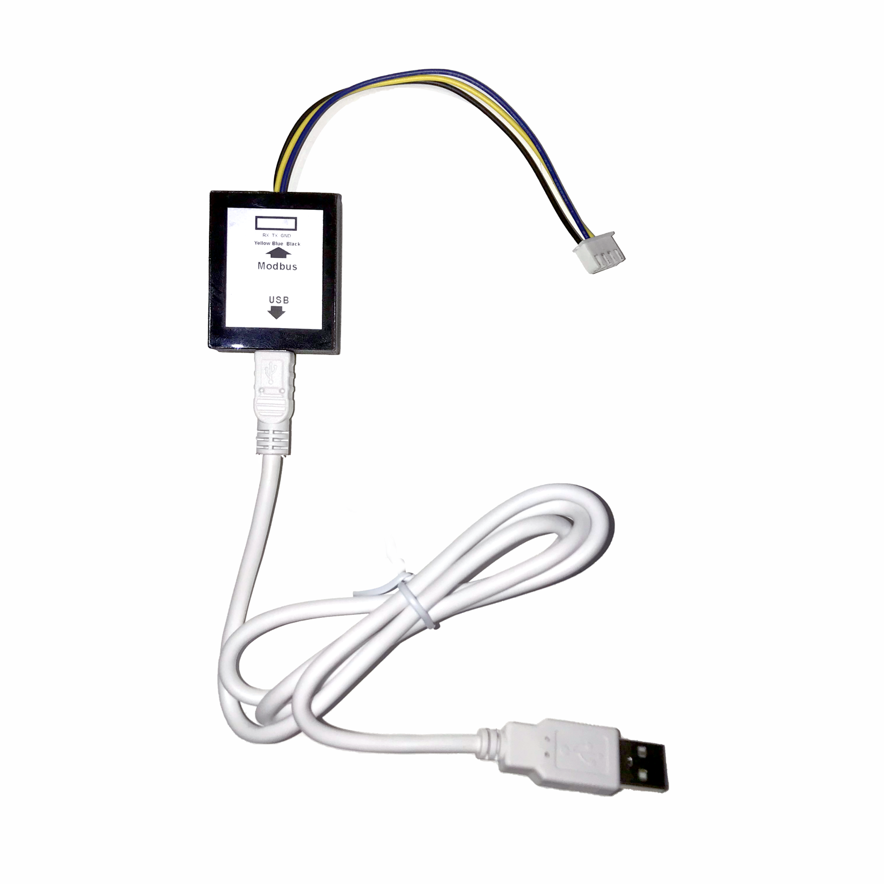
When starting the power supply, the LoRaWAN sensor has 60 seconds to allow configuration to operate via the Configuration Cable with the Modbus RTU protocol. After 60 seconds, the first packet will be sent, then the LoRaWAN sensor will send the next packets in the following cases:
- Case 1:
- When it reaches the frequency of taking data, the LoRaWAN sensor will wake up to measure and calculate. Then:
- If the measured value exceeds the High or Low setting thresholds, the packet will be sent to the Gateway and then asleep;
- If NOT then sleep without sending data.
NOTE:
Once sending the data to Gateway by this alarm event, the timer of sending time interval will be reset;
- When it reaches the frequency of taking data, the LoRaWAN sensor will wake up to measure and calculate. Then:
- Case 2: When the sending time interval is reached, the LoRaWAN sensor wakes up to measure and calculate and send data to Gateway immediately, regardless of value.
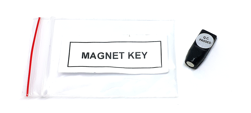
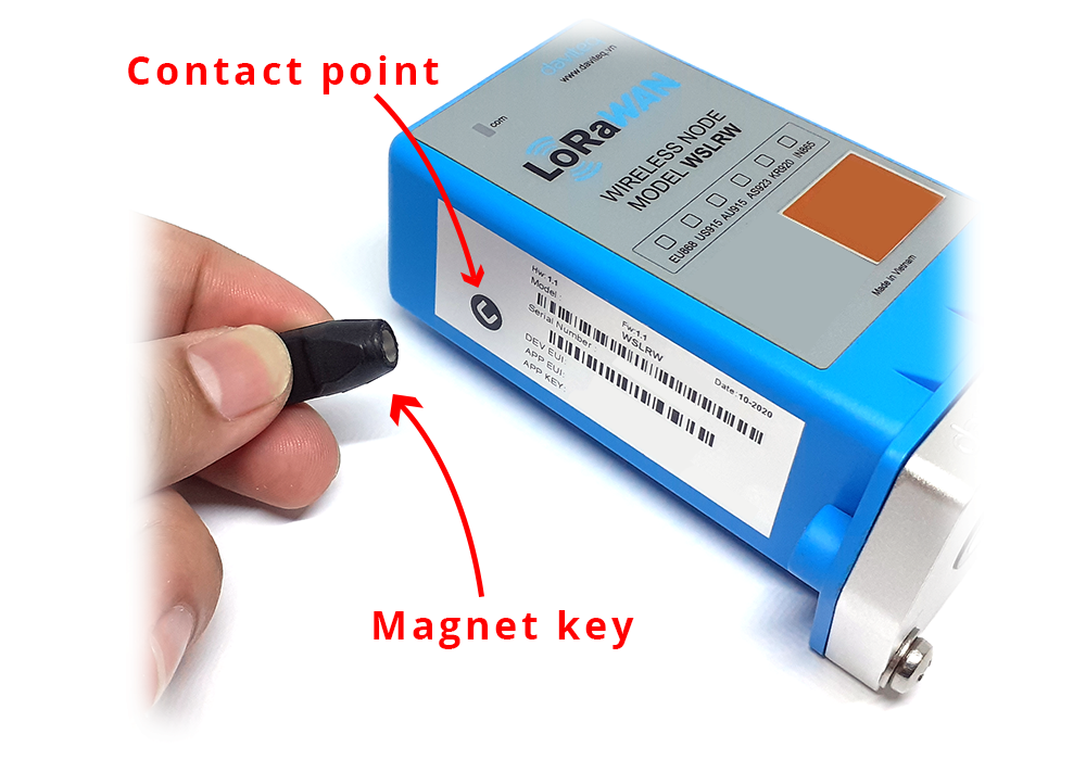
- Case 3: By using the magnet key, the LoRaWAN sensor can be triggered to send data to Gateway immediately.
NOTE:
The time between sending data for Class A is at least 3 seconds
 |
 |
4.3 Principle of operation LoRaWAN Network
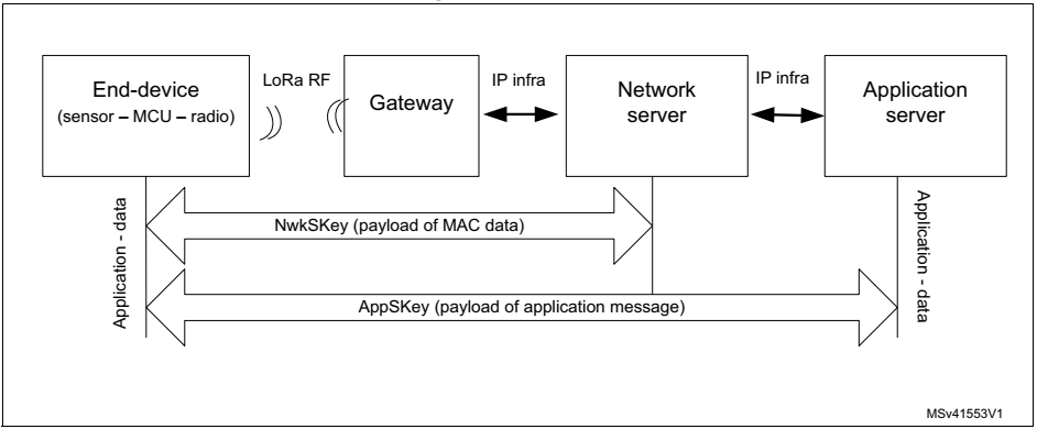
The LoRaWAN Gateway function is Packet Forwarder so:
- Between Gateway and End Device: Gateway receives data packets from End Device via RF connection, so it is recommended to configure Radio parameters (Note: the packet that Gateway receives is encrypted)
- Between Gateway and Network Server: Gateway forwards data packets to the Network server via an IP connection, so it is recommended to configure Network parameters such as Server Address, Server Uplink Port, Server Downlink Port, ..
LoRaWAN Network is secured as follows:
- Network section key (NwkSKey) to ensure the security of communications on the Network
- Application session key (AppSKey) to ensure data security between End Device and Application Server
- Special keys of the device such as DevEUI, AppEUI, Gateway EUI, Device Address. Therefore, the data packet that the Gateway receives is encrypted and decrypted on the Application server.
To End Device connect to the Network server, you need to register in the following two ways:
- Activation with OTAA (Over-the-Air activation): is the process of joining the Network automatically. Previously, both End Device and Application Server installed the same DevEUI code, AppEUI and AppKey. During activation, AppKey will generate 2 security keys for End Device and Network, which are:
- Network session key (NwkSKey): is the key to secure communication commands on MAC layer between End Device and Network server.
- Application session key (AppSKey): is the key to secure data packets between End Device and Application server.
ATTENTIONS:
* OTAA mode must be successfully activated in order for the End Device to send data packets to the Network through the Gateway;
* OTAA mode only need to activate once, if the device is reset or battery replacement, it will activate OTAA again;
* When the End Device is connected to the Network server, whether the Gateway is reset or the power is restarted, it will not need to activate OTAA.
- Activation by ABP (Activation by Personalization): is the process of joining Network manually. Device Address, Network session key (NwkSKey) and Application session key (AppSKey) codes must be stored inside the End Device and Application server, so when the End Device sends data packets to the Network server, it will also send the security codes to activated.
4.4 Configure the LoRaWAN Network
4.4.1 Configure End Device operation according to OTAA
Configuration parameters for the End Device to be activated by OTAA as the table below:
|
Parameter settings |
Setting value (example) |
Description |
|
Region code |
AS923 |
The area is located in the LoRa Alliance |
|
Center Frequency |
923400000 |
Center frequency |
|
Join Mode |
OTAA |
Device activation type on Network Server |
|
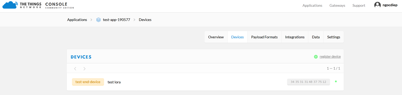
DevEUI |
34 35 31 31 4B 37 75 12 |
Device ID's unique ID number => Set this ID number for the Application server |
|
AppEUI |
70 B3 D5 7E D0 02 D5 0B |
Application server's unique ID number (random or user generated) |
|
AppKey |
2B 7E 15 16 28 AE D2 A6 AB F7 15 88 09 CF 4F 3C |
Key Number for generating 2 NwkSKey and AppSKey security keys created by the user (factory-created by default) |
ATTENTIONS:
* The AppEUI number from Application Server => then installed for the End Device. AppEUI is randomly generated by the Application server or by the user;
* The number of AppKeys during OTAA activation will generate two security keys, Lora NwkSKey and AppSKey, which are used for both End Device and Network.
4.4.2 Configure End Device operation according to ABP
Configuration parameters for the End Device to be activated by ABP as the table below:
|
Parameter settings |
Setting value (example) |
Description |
|
Region code |
AS923 |
The area is located in the LoRa Alliance |
|
Center Frequency |
923400000 |
Center frequency |
|
Join Mode |
ABP |
Device activation type on Network Server |
|
Device Address |
12 34 56 78 |
End Device Address created by Application server |
|
NwkSKey (Network session key) |
2B 7E 15 16 28 AE D2 A6 AB F7 15 88 09 CF 4F 3C |
NwkSKey number created by the user to install and use for both End Device and Application Server |
|
AppSKey (Application session key) |
2B 7E 15 16 28 AE D2 A6 AB F7 15 88 09 CF 4F 3C |
AppSKey number generated by the user to install for both End Device and Application Server |
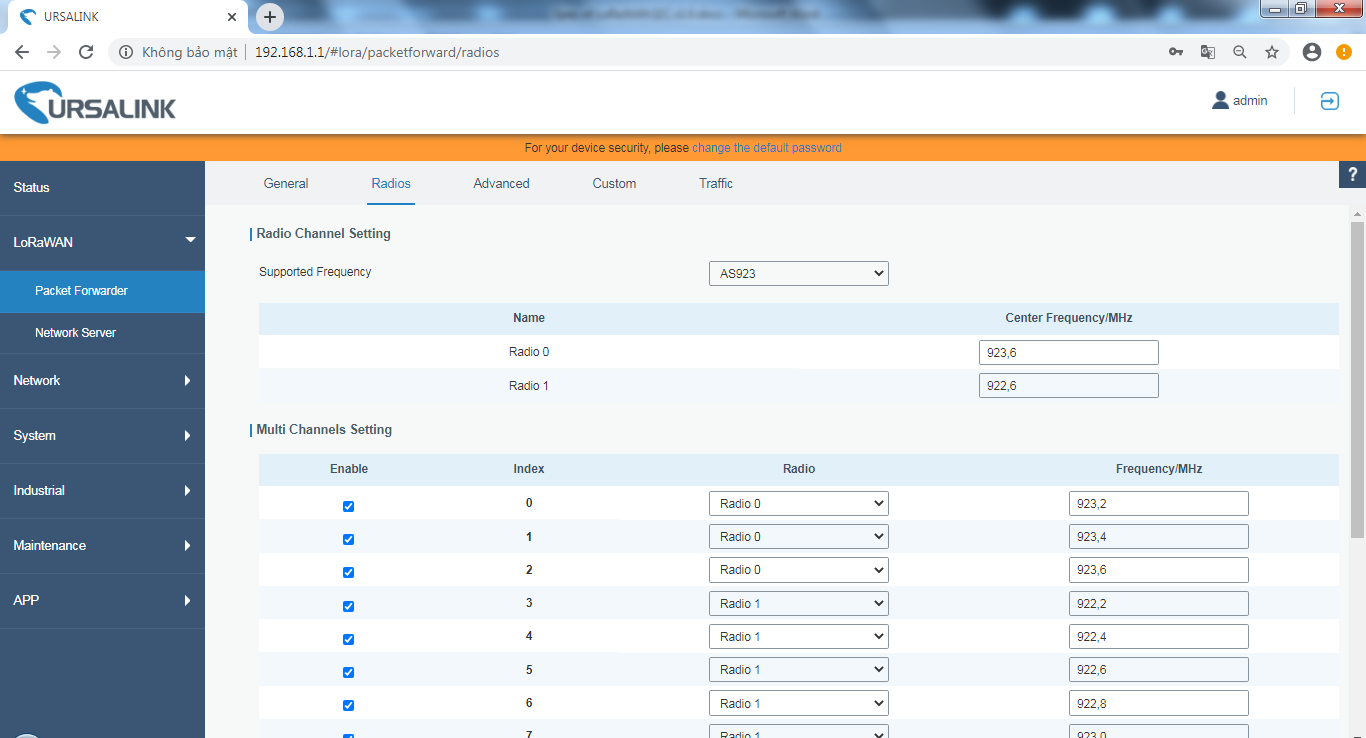
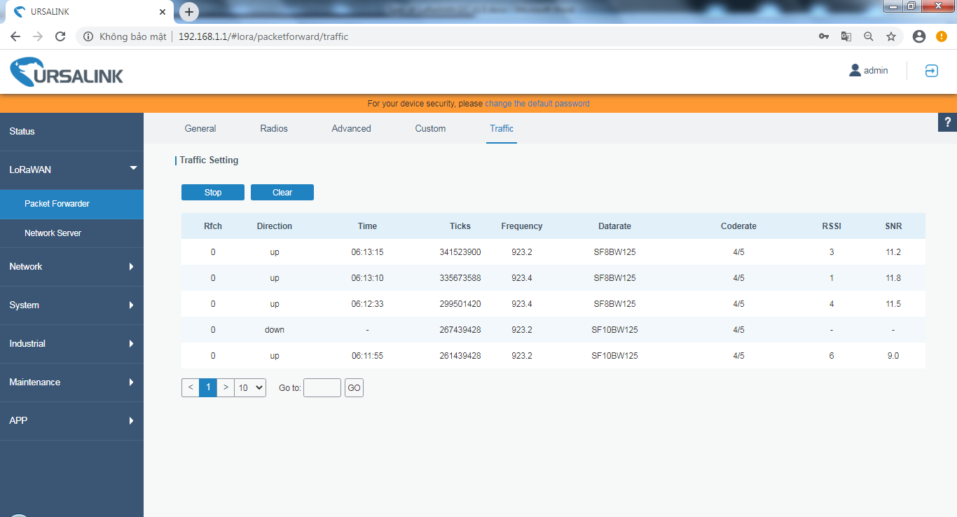
4.4.3 Configure Gateway operations
4.4.3.1 Configure the Gateway to receive data packets from the End Device.
Radio settings need to be set as:
* Region code: AS923, KR920, AU915, US915, EU868, IN865, RU864
* Center Frequency, Channels, Bandwidth (recommends using the default configuration created by the system)
Let's take an example to configure the Gateway operation of URSALINK (Model: UG85-L00E-915)
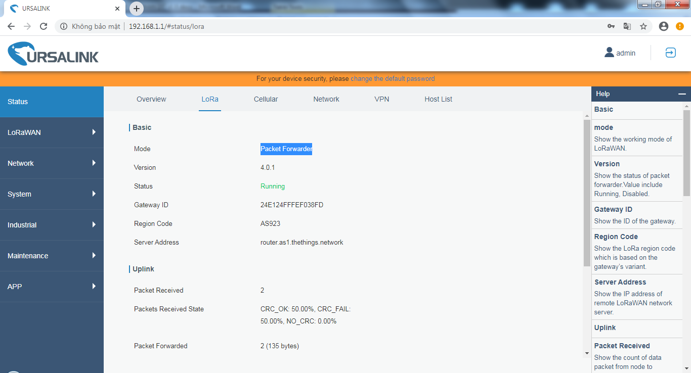

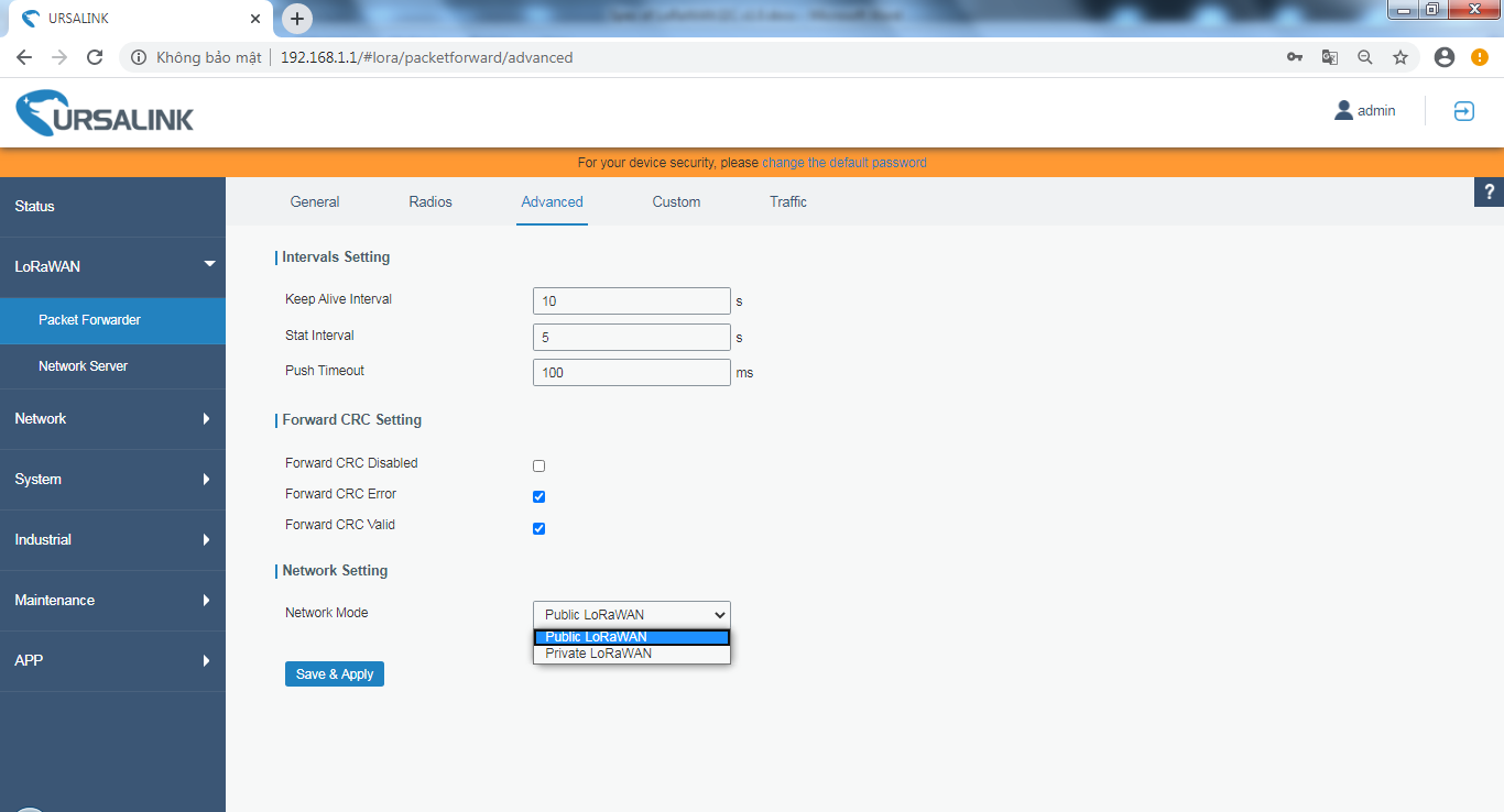
4.4.3.2 Configure the Gateway to communicate with the Public Network Server
Let's take an example of configuring Gateway UG85 to connect with "thethingsnetwork.org" in Asia:
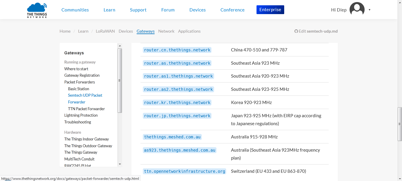
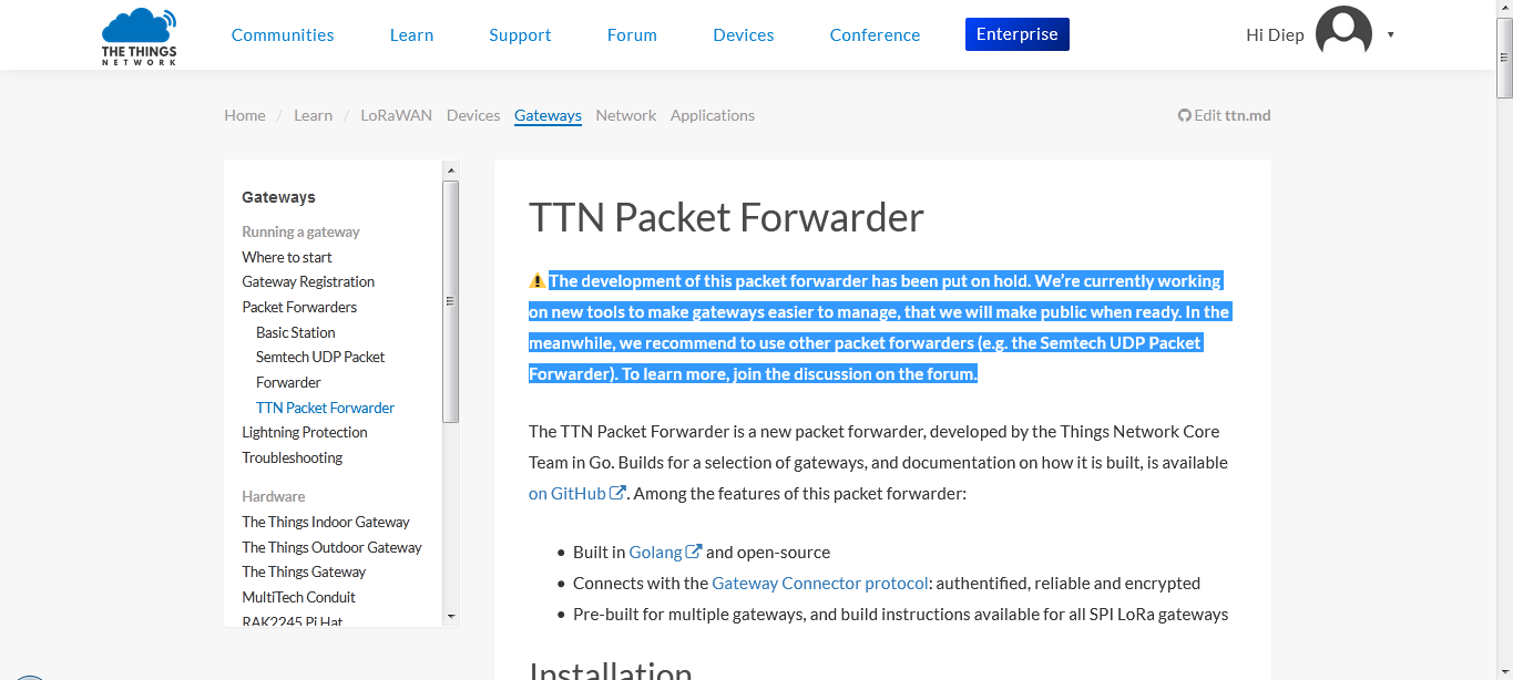
Currently thethingsnetwork only supports the connection protocol with Gateway is Semtech UDP Packet Forwarder.
https://www.thethingsnetwork.org/docs/gateways/packet-forwarder/semtech-udp.html
|
Parameter settings |
Setting value (example) |
Description |
|
Gateway EUI |
24e124fffef038fd |
Gateway's unique ID number |
|
Server Address |
router.as1.thethings.network |
|
|
Server Uplink Port |
1700 |
|
|
Server Downlink Port |
1700 |
|
|
Network mode |
Public LoRaWAN |
|

4.4.4 Register the Application server on the Public Network "thethingsnetwork.org"
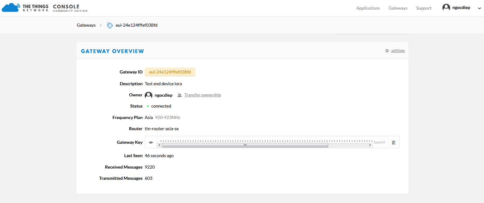
4.4.4.1 Register the Gateway on Public Network "thethingsnetwork.org" as shown below:
- The current network only supports the Gateway connection protocol, "Semtech UDP protocol" is Semtech UDP Packet Forwarder.
- Then power the Gateway and observe the message "Status: connected" => Registration of the Gateway on the Application successfully.

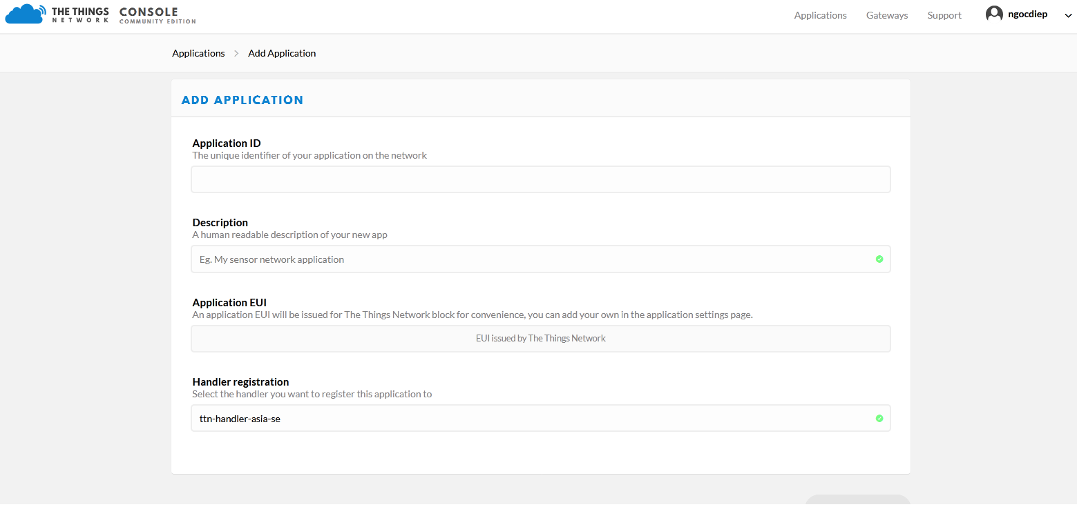
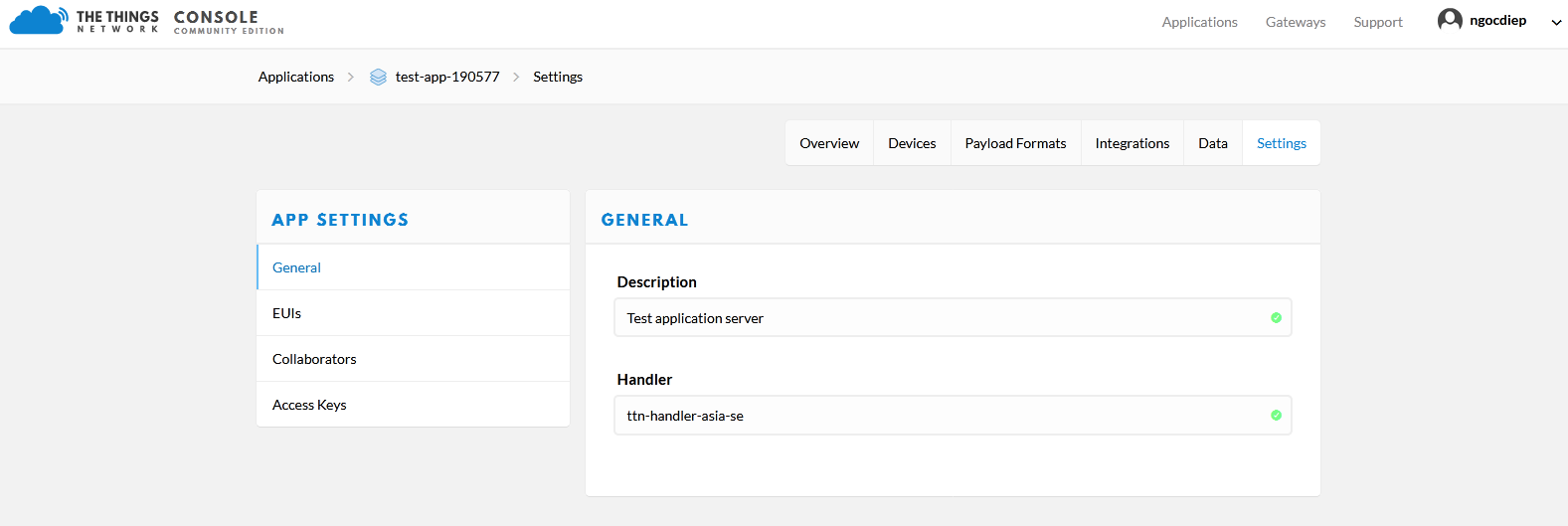
4.4.4.2 Register Application on Public Network "thethingsnetwork.org" as shown below:
4.4.4.3 Register End Device on Application:


4.5 LED meaning
-
RED LED:
- Fixed ON: due to noise caused peripheral components (i2c, spi, uart, timer, rtc, wdt, ...) do not initialize.
- Flashing 10ms ON / 10s OFF: Activation by OTAA on the Network server failed.
- Flashing 10ms ON / 2s OFF: Sending data packet to Gateway failed.
- GREEN LED: Flashing 100ms ON / OFF when sending data packet to Gateway.
- BLUE LED:
-
- Flashing 1s ON / 1s OFF for the first 60 seconds when booting (insert batteries or connected external sources), after 60 seconds OFF.
- ON during the LoRaWAN sensor receives data packets from the Network server and OFF when received.
4.6 Process of measurement
When the LoRa sensor wakes up, it will supply power to the external sensor module so that the module can start measuring. After measuring it will turn off the power to the module.
The measured value is the raw value of the sensor module, which can be ambient temperature, ambient humidity, etc.
The measurement value can be scaled according to the following formula:
Y = aX + b
-
-
-
-
- X: the raw value from module sensor
- Y: the calculated value will be sent to Sigfox base station in the payload data.
- a: constant (default value is 1)
- b: constant (default value is 0)
-
-
-
4.7 Payload Data
|
Sensor type (1 byte) |
Status (1 byte) |
1st - Parameter (4 bytes) |
2nd - Parameter (4 bytes) |
Meaning of Data in the Payload
| Data | Size (byte) | Bit | Format | Meaning |
|
Sensor type |
1 |
all |
Uint8 |
Sensor type = 0x02 means LoRaWAN Node with I2C Humidity & Temperature |
|
Status: battery level |
1 |
Bit 7 and 6 |
Uint8 |
Battery capacity in 04 levels 11: battery level 4 (99%) 10: battery level 3 (60%) 01: battery level 2 (30%) 00: battery level 1 (10%) |
|
Status: error |
|
Bit 5 and 4 |
|
Node status 01: error 00: no error |
|
Status: alarm 1 |
|
Bit 3 and 2 |
|
Alarm status of 1st - Parameter (Y1 value) 11 : Hi alarm |
|
Status: alarm 2 |
|
Bit 1 and 0 |
|
Alarm status of 2nd - Parameter (Y2 value) 11 : Hi alarm |
|
1st - Parameter |
4 |
all |
Float |
Y1 value: humidity value (%) |
|
2nd - Parameter |
4 |
all |
Float |
Y2 value: temperature value (oC) |
5. Configuration
Serial port configuration on the computer:
* COMPort, Baudrate: 9600, Parity: None, Stop bit: 1, Data bit: 8
* Modbus RTU: Reading data by Function 3 / Writing data by Function 16.
5.1 Step to configure
NOTE:
The Modbus configuration can only be performed in the first 60s after power up the LoRaWAN sensor. After 60s, if user can not finish the configuration process, user need to reset the power of LoRaWAN sensor again, by removing battery in at least 15s.
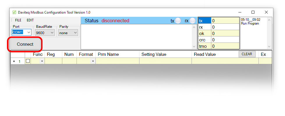
Step 1: Install the Modbus Configurator Software in the link below
https://filerun.daviteq.com/wl/?id=qK0PGNbY1g1fuxTqbFW9SXtEvCw7bpc6
How to use the Modbus configuration software
Step 2: Plug the configuration cable to computer via usb port and install the driver;
Step 3: Open the plastic housing with L hex key to unscrew M4 screws at the side of housing
Step 4: Plug the connector to the configuration port;
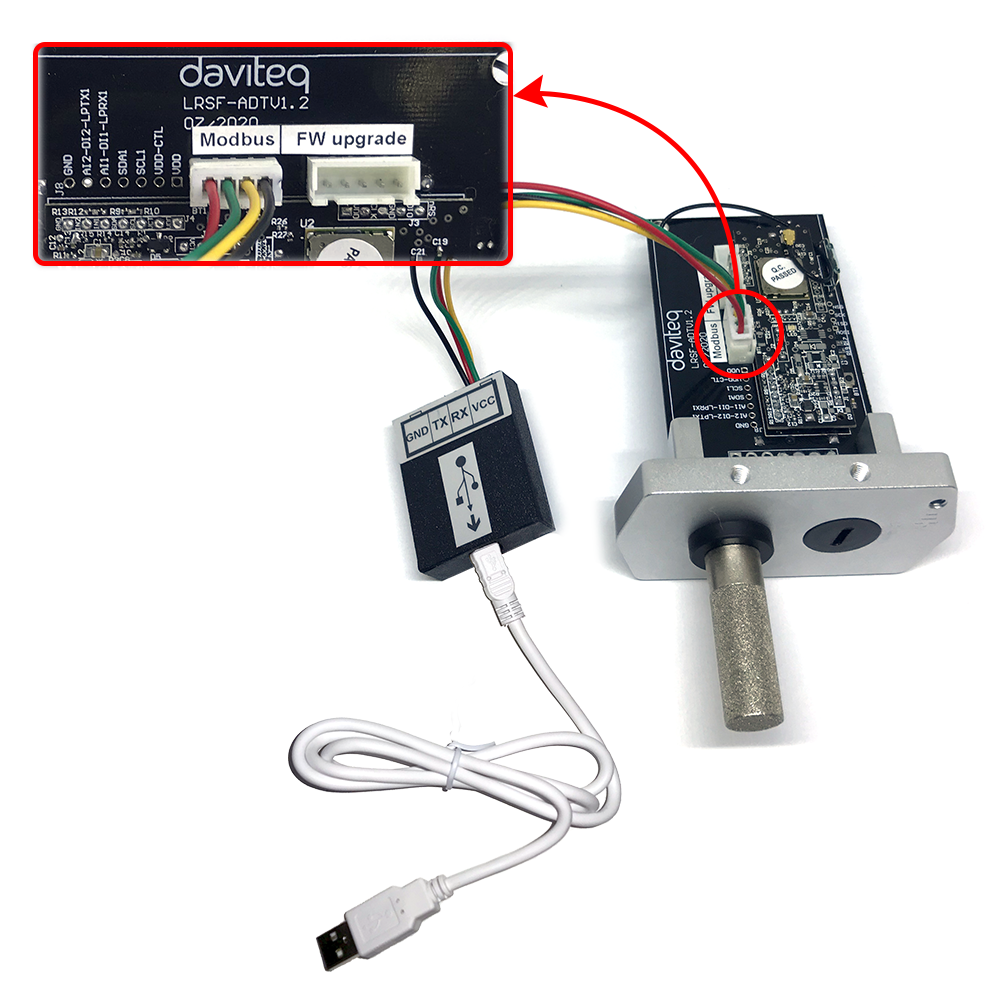
Step 5: Import the configuration file by importing the csv file: Go to MENU: FILE / Import New / => select the file with name CONFIGURATION TEMPLATE FILE FOR LORAWAN SENSOR FW1.0.csv (in the link below). Then click Connect;
CONFIGURATION TEMPLATE FILE FOR LORAWAN SENSOR FW1.0
To write new value to the device:
First, you need to write the password in "password for setting", after reading the value to check ok, you can write the new value AppEUI, AppKey, ...
You only have 60 seconds after plugging the configuration cable or the power supply into the device for configuration.
5.2 Register table
Here is the table of Data will be read by Modbus tool
|
Modbus Register (Decimal) |
Modbus Register (Hex) |
Function Code |
# of Registers |
Description |
Range |
Default |
Format |
Property |
Comment |
|
0 |
0 |
3 |
5 |
device info |
WSLRW-I2C |
string |
Read |
Wireless Sensor LoRaWAN - I2C |
|
|
5 |
5 |
3 |
4 |
firmware version |
1.00ddmm |
string |
Read |
ddmm = day / month |
|
|
9 |
9 |
3 |
2 |
hardware version |
1.10 |
string |
Read |
||
|
11 |
B |
3 |
4 |
lorawan protocol version |
01.00.03 |
string |
Read |
lorawan v1.0.3 |
|
|
15 |
F |
3 |
6 |
application version |
01.03.00.00 |
string |
Read |
application server v1.3.0.0 |
|
|
21 |
15 |
3 |
6 |
mac layer version |
04.04.02.00 |
string |
Read |
mac layer v4.4.2.0 |
|
|
27 |
1B |
3 |
4 |
deviceEUI |
hex |
Read |
End Device's EUI number, used to register the product on the Network Server by OTAA |
||
|
31 |
1F |
3 |
4 |
lora appEUI |
hex |
Read |
Application server's EUI number is used to register the product on the Network Server by OTAA |
||
|
35 |
23 |
3 |
8 |
lora appKey |
hex |
Read |
The number of keys used to create two security keys of the End Device, used to register the product on the Network Server by OTAA |
||
|
43 |
2B |
3 |
8 |
lora nwkSkey |
hex |
Read |
key number encrypts the communication command of the MAC layer of the End Device, which is used to register the product on the Network Server by ABP |
||
|
51 |
33 |
3 |
8 |
lora appSkey |
hex |
Read |
End Device data encryption key number, used to register the product on the Network Server by ABP |
||
|
59 |
3B |
3 |
2 |
device address |
0 |
uint32 |
Read |
End Device address created by Application server, used to register the product on the Network server by ABP |
|
|
61 |
3D |
3 |
2 |
network ID |
0 |
uint32 |
Read |
Network server ID number, used to register the product on the Network server by ABP |
|
|
63 |
3F |
3 |
2 |
join mode |
OTAA |
string |
Read |
OTAA: Over-the-Air activation, ABP: Activation by Personalization |
|
|
65 |
41 |
3 |
4 |
network mode |
PUBLIC |
string |
Read |
PUBLIC, PRIVATE |
|
|
69 |
45 |
3 |
3 |
region code |
AS923 |
string |
Read |
1: AS923, 2: KR920, 3: AU915, 4: US915, 5: EU868, 6: IN865, 7: RU864, 8: CN779, 9: CN470, 10: EU433 |
|
|
72 |
48 |
3 |
4 |
data rate |
DR2:980 |
string |
Read |
DR0:250, DR1:440, DR2:980, DR3:1760, DR4:3125, DR5:5470 |
|
|
76 |
4C |
3 |
3 |
bandwidth |
BW125 |
string |
Read |
BW125, BW250, BW500 |
|
|
79 |
4F |
3 |
2 |
spread factor |
SF10 |
string |
Read |
SF12, SF11, SF10, SF9, SF8, SF7 |
|
|
81 |
51 |
3 |
4 |
activation of ADR |
ADR OFF |
string |
Read |
ADR ON, ADR OFF |
|
|
85 |
55 |
3 |
1 |
class |
A |
string |
Read |
||
|
103 |
67 |
3 |
1 |
sensor type |
1-255 |
uint16 |
Read |
1-254: sensor type, 255: no sensor |
|
|
104 |
68 |
3 |
1 |
battery level |
0-3 |
uint16 |
Read |
4 levels of battery capacity status |
|
|
105 |
69 |
3 |
1 |
error status |
0-1 |
uint16 |
Read |
Error code of sensor, 0: no error, 1: error |
|
|
106 |
6A |
3 |
1 |
prm1 alarm status |
0-2 |
uint16 |
Read |
Alarm status of parameters 1, 0: none, 1: Low, 2: High |
|
|
107 |
6B |
3 |
1 |
prm2 alarm status |
0-2 |
uint16 |
Read |
Alarm status of parameter 2 |
|
|
108 |
6C |
3 |
2 |
prm1 value |
float |
Read |
Parameter value 1 |
||
|
110 |
6E |
3 |
2 |
prm2 value |
float |
Read |
Parameter value 2 |
||
|
112 |
70 |
3 |
1 |
battery % |
10%, 30%, 60%, 99% |
uint16 |
Read |
% Value of battery capacity |
|
|
113 |
71 |
3 |
2 |
battery voltage |
0-3.67 vdc |
float |
Read |
Value of battery voltage |
|
|
115 |
73 |
3 |
2 |
mcu temperature |
oC |
float |
Read |
Temperature value of RF module |
|
|
117 |
75 |
3 |
1 |
mcu vref |
0-3.67 vdc |
uint16 |
Read |
Vref value of RF module |
|
|
118 |
76 |
3 |
1 |
button1 status |
0-1 |
uint16 |
Read |
Button state, 0: No button pressed, 1: Button pressed |
|
|
119 |
77 |
3 |
1 |
button2 status |
0-1 |
uint16 |
Read |
Button status, 0: No magnetic sensor detected, 1: Magnetic sensor detected |
|
Modbus Register (Decimal) |
Modbus Register (Hex) |
Function Code |
# of Registers |
Description |
Range |
Default |
Format |
Property |
Comment |
|
256 |
100 |
3 / 16 |
1 |
modbus address |
1-247 |
1 |
uint16 |
R/W |
Modbus address of the device |
|
257 |
101 |
3 / 16 |
1 |
modbus baudrate |
0-1 |
0 |
uint16 |
R/W |
0: 9600, 1: 19200 |
|
258 |
102 |
3 / 16 |
1 |
modbus parity |
0-2 |
0 |
uint16 |
R/W |
0: none, 1: odd, 2: even |
|
259 |
103 |
3 / 16 |
9 |
serial number |
string |
R/W (Password) |
|||
|
268 |
10C |
3 / 16 |
2 |
password for setting |
uint32 |
R/W (Password) |
password 190577 |
||
|
270 |
10E |
3 / 16 |
4 |
lora appEUI |
hex |
R/W (Password) |
Application server's EUI number, used to register the product on the Network Server by OTAA |
||
|
274 |
112 |
3 / 16 |
8 |
lora appKey |
hex |
R/W (Password) |
The number of keys used to create two security keys of the End Device, used to register the product on the Network server by OTAA |
||
|
282 |
11A |
3 / 16 |
8 |
lora nwkSkey |
hex |
R/W (Password) |
key number encrypts the communication command of the MAC layer of the End Device, which is used to register the product on the Network Server by ABP |
||
|
290 |
122 |
3 / 16 |
8 |
lora appSkey |
hex |
R/W (Password) |
End Device data encryption key number, used to register the product on the Network Server by ABP |
||
|
298 |
12A |
3 / 16 |
2 |
device address |
uint32 |
R/W (Password) |
End Device address created by Application server, used to register the product on the Network server by ABP |
||
|
300 |
12C |
3 / 16 |
2 |
network ID |
uint32 |
R/W (Password) |
Network server ID number, used to register the product on the Network server by ABP |
||
|
302 |
12E |
3 / 16 |
1 |
activation mode |
0-1 |
1 |
uint16 |
R/W (Password) |
1: OTAA (Over-the-Air Activation), 0: ABP (Activation by Personalization) |
|
304 |
130 |
3 / 16 |
1 |
application port |
1-255 |
1 |
uint16 |
R/W (Password) |
Port 224 is reserved for certification |
|
317 |
13D |
3 / 16 |
1 |
region |
1-7 |
1 |
uint16 |
Read/Write(Password) |
1: AS923, 2: KR920, 3: AU915, 4: US915, 5: EU868, 6: IN865, 7: RU864, 8: CN779, 9: CN470, 10: EU433 |
|
318 |
13E |
3 / 16 |
1 |
data rate |
7 |
uint16 |
R/W (Password) |
0: 250 bps, 1: 440 bps, 2: 980 bps, 3: 1760 bps, 4: 3125 bps, 5: 5470 bps |
|
|
319 |
13F |
3 / 16 |
1 |
tx power |
2-20 |
16 |
uint16 |
R/W (Password) |
tx power: 2,4,6,8,10,12,14,16,18,20 |
|
320 |
140 |
3 / 16 |
1 |
adaptative data rate |
0-1 |
0 |
uint16 |
R/W (Password) |
Automatically adjust data rate, 0: disable, 1: enable |
|
334 |
14E |
3 / 16 |
2 |
cycle send data |
900 |
uint32 |
R/W |
sec (data sending cycle) |
|
|
338 |
152 |
3 / 16 |
1 |
alarm limt |
44 |
uint16 |
R/W |
limit the number of events / day |
|
|
340 |
154 |
3 / 16 |
2 |
sensor1: sampling_rate |
120 |
uint32 |
R/W |
sec (frequency of data taken from sensor 1) |
|
|
348 |
15C |
3 / 16 |
2 |
prm1: a |
1 |
float |
R/W |
Scale parameter "a" of sensor 1 |
|
|
350 |
15E |
3 / 16 |
2 |
prm1: b |
0 |
float |
R/W |
Scale parameter "b" of sensor 1 |
|
|
354 |
162 |
3 / 16 |
2 |
prm1: High Threshold |
100000 |
float |
R/W |
High threshold value of sensor 1 |
|
|
356 |
164 |
3 / 16 |
2 |
prm1: High Hysteresis |
10000 |
float |
R/W |
High hysteresis value of sensor 1 |
|
|
358 |
166 |
3 / 16 |
2 |
prm1: Low Threshold |
0 |
float |
R/W |
Low threshold value of sensor 1 |
|
|
360 |
168 |
3 / 16 |
2 |
prm1: Low Hysteresis |
10000 |
float |
R/W |
Low hysteresis value of sensor 1 |
|
|
362 |
16A |
3 / 16 |
2 |
prm1: High Cut |
100000 |
float |
R/W |
Upper limit value of sensor 1 |
|
|
364 |
16C |
3 / 16 |
2 |
prm1: Low Cut |
0 |
float |
R/W |
Lower limit value of sensor 1 |
|
|
366 |
16E |
3 / 16 |
2 |
prm2: a |
1 |
float |
R/W |
Scale parameter "a" of sensor 2 |
|
|
368 |
170 |
3 / 16 |
2 |
prm2: b |
0 |
float |
R/W |
Scale parameter "b" of sensor 2 |
|
|
372 |
174 |
3 / 16 |
2 |
prm2: High Threshold |
100000 |
float |
R/W |
High threshold value of sensor 2 |
|
|
374 |
176 |
3 / 16 |
2 |
prm2: High Hysteresis |
10000 |
float |
R/W |
High hysteresis value of sensor 2 |
|
|
376 |
178 |
3 / 16 |
2 |
prm2: Low Threshold |
0 |
float |
R/W |
Low threshold value of sensor 2 |
|
|
378 |
17A |
3 / 16 |
2 |
prm2: Low Hysteresis |
10000 |
float |
R/W |
Low hysteresis value of sensor 2 |
|
|
380 |
17C |
3 / 16 |
2 |
prm2: High Cut |
100000 |
float |
R/W |
Upper limit value of sensor 2 |
|
|
382 |
17E |
3 / 16 |
2 |
prm2: Low Cut |
0 |
float |
R/W |
Lower limit value of sensor 2 |
6. Installation
6.1 Example application
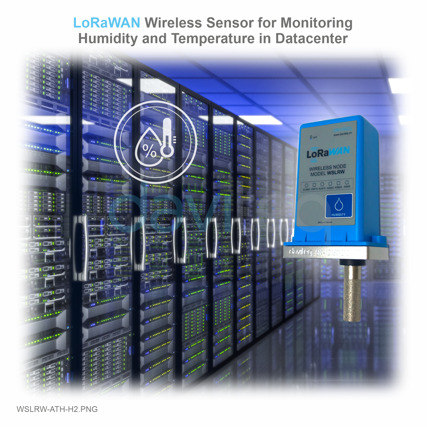 |
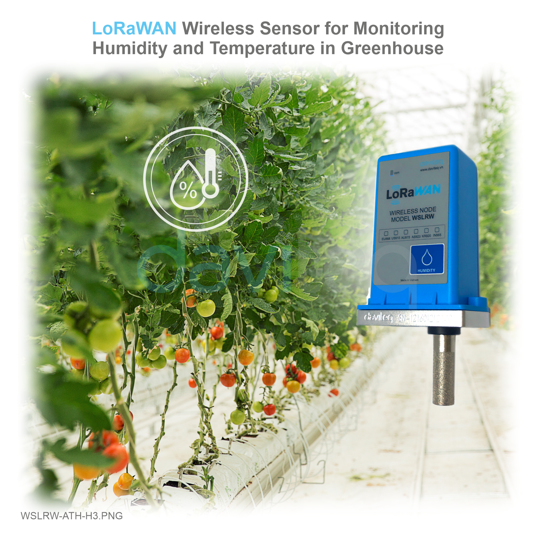 |
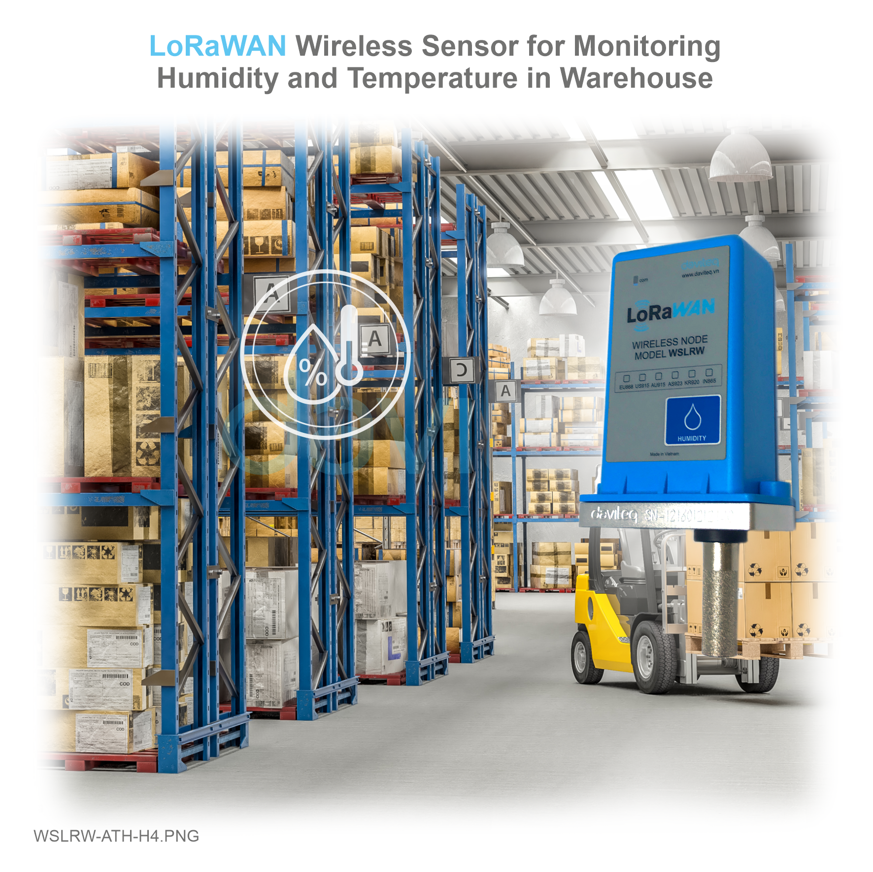 |
 |
6.2 Installation location
To maximize the distance of transmission, the ideal condition is Line-of-sight (LOS) between the LoRaWAN sensor and Gateway. In real life, there may be no LOS condition. However, the LoRaWAN sensor still communicates with Gateway, but the distance will be reduced significantly.
ATTENTION:
DO NOT install the LoRaWAN sensor or its antenna inside a completed metallic box or housing, because the RF signal can not pass through the metallic wall. The housing is made from Non-metallic materials like plastic, glass, wood, leather, concrete, cement…is acceptable.
6.3 Battery installation
Steps for battery installation:
Step 1: Using L hex key to unscrew M4 screws at the side of housing and carefully pull out the top plastic housing in the vertical direction
Step 2: Insert 02 x AA 1.5VDC battery, please take note the poles of battery
ATTENTION:
REVERSED POLARITY OF BATTERIES IN 10 SECONDS CAN DAMAGE THE SENSOR CIRCUIT!!!

Step 3: Insert the top plastic housing and locking by L hex key
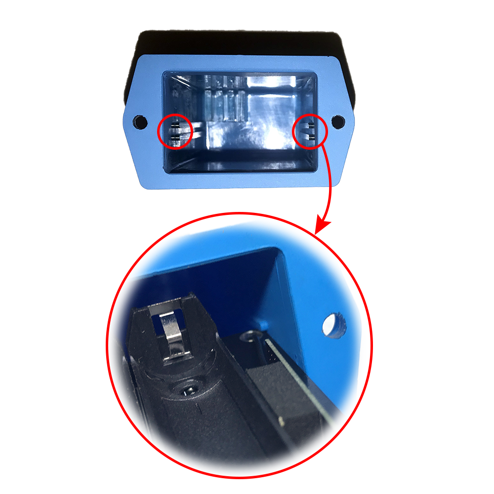
ATTENTION:
When reinstalling the cover, pay attention to put the PCB edge into the middle slot of the box inside as shown below)
7. Troubleshooting
| No. | Phenomena | Reason | Solutions |
| 1 | The BLUE LED does not blink when the battery is installed |
Insert the battery in the opposite direction |
Insert the battery in the correct way |
| 2 | The RED LED is always on | Due to noise, the peripheral components (i2c, spi, uart, ..) of RF module cannot be initialized | After 30s the node will automatically reset. If the noise causes the Watchdog not to initialize, remove the battery and wait for more than 10 seconds, then insert the battery again |
| 3 | The RED LED blinks continuously (10ms ON / 2s OFF) and the Node does not send RF. After more than 10 sending cycles, the Node will automatically reset |
|
|
| 4 | RED LED blinks continuously (10ms ON / 2s OFF) and Node sends RF continuously 3s / time but no data. After more than 10 sending cycles, the Node will automatically reset |
Node runs dummy sending mode => sent by Gateway to send Downlink packets when users clear Uplink and Downlink counter values on Network Server (build in Gateway) when activated by ABP |
Configuration enabled by OTAA |
| 5 | The RED LED flashes 10ms ON / 10s OFF and the Node does not send RF | Node activation by OTAA on Network server has not been successful |
Using Margnet-Key to force Node to send RF continuously for 3 seconds / time => when activating by OTAA successfully, the GREEN LED will blink after sending RF |
| 6 | The node sent RF successfully but the GREEN LED did not blink | LED is broken | Warranty to replace LED |
| 7 | The data packet taken from the Gateway has an incorrect value | The data package is encrypted | Get the decoded packet on the Application Server |
| 8 | Node sends RF and activates by ABP, on Gateway receives data but Application server has no data | The application server still stores the counter values of the previous Uplink and Downlink | Delete the counter values of Uplink and Downlink on the Application server |
| 9 | The node does not send RF and the RF module is hot |
|
Warranty or replacement |
| 10 |
Node does not send RF to Gateway according to the alarm, LED does not blink |
|
|
| 11 |
Node does not send RF to Gateway when activated by the magnetic switch, LED does not blink |
Magnetic switch has malfunctioned |
Read the status of the magnetic switch via modbus (when powering or attaching the battery) to see if the magnetic switch is working. |
| 12 |
Node has blinked LED GREEN when sending RF but the Gateway or Application server cannot received |
|
|
| 13 | The value of the sensor is 0 and sensor_type = 0xFF | Lost connection with the sensor |
|
| 14 | RSSI is weak and often loses data |
|
|
8. Support contacts
|
Manufacturer
Daviteq Technologies Inc Email: info@daviteq.com | www.daviteq.com
|
Distributor in Australia and New Zealand
Templogger Pty Ltd Tel: 1800 LOGGER Email: contact@templogger.net |

No Comments