
I. QUICK GUIDE
This document is applied for the following products
|
SKU |
GWIND |
|
SKU name |
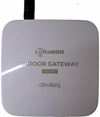
Indoor LoRaWAN gateway |
|
Item Code
|
GWIND-8-4G-WET; GWIND-8-4G-WET-RN; GWIND-8-4GEUX-WET; GWIND-8-4GEUX-WET-RN; GWIND-8-WET; GWIND-8-WET-RN; GWIND-9-4G-WET; GWIND-9-4G-WET-RN; GWIND-9-4GEUX-WET; GWIND-9-4GEUX-WET-RN; GWIND-9-WET; GWIND-9-WET-RN |
1.1 Functions Change Log
| Firmware version
|
Hardware version |
Release Date |
Function Change |
|
9 |
2 | 02 Jun 26 |
1. Add Wi-Fi Configuration Mode (Access Point) on startup. 2. Change Packet Forwarder configuration. 3. Update LTE Watcher recovery mechanism. |
1.2 Introduction
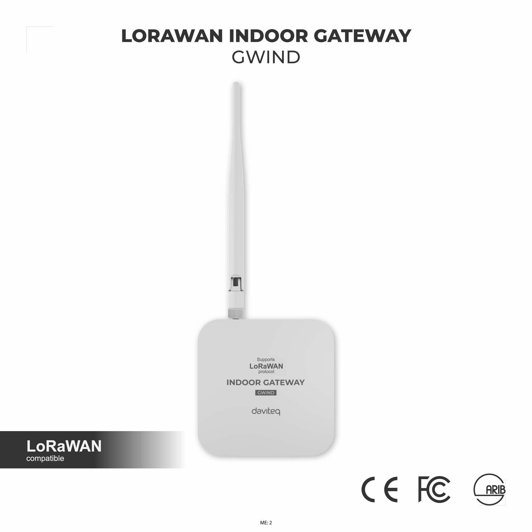
GWIND is a LoRaWAN® Gateway designed for indoor installation, used in projects such as Smart Factory, Smart Agriculture, Smart Building, Smart Residential Area, Smart City... It simultaneously supports 8 connection channels to help receive a large number of packets from surrounding LoRaWAN sensors. The connection distance to the LoRaWAN sensors is up to 10km (depending on the environment and sensor types). It supports common communications such as Ethernet, LTE, WiFi. LoRa frequency support 863∼870MHz/ 902∼928MHz. This LoRaWAN Gateway is widely used in applications such as reading water meters, electricity meters, gas meters, environmental monitoring, smart farms, and smart factories...
1.3 Application Notes
For Applications
Automatic Ventilation System, Condition Based Monitoring, Energy Monitoring, Facility Monitoring, Fuel Monitoring, Gas Leakage Detection, Indoor Air Quality Monitor, Machine Health Monitoring, Odor Monitoring, People Counting, Production Monitoring, Temperature Monitoring, Vibration Monitoring, Warehouse Monitoring, Water Meter Reading
Notes
When selecting a LoRaWAN gateway, it is essential to choose the correct frequency band based on your region (e.g., 920–925 MHz or 863–870 MHz depending on local regulations). Ensure the gateway supports suitable network connectivity options such as Ethernet, Wi-Fi, or 4G/LTE, depending on the availability and reliability of internet access at the installation site. Also, consider whether the deployment is indoor or outdoor. The indoor gateways are compact and economy, while outdoor gateways should be weatherproof (e.g., IP67-rated) and capable of wider coverage. Choosing the right version ensures stable performance and long-term reliability.
1.4 What's in the Package?
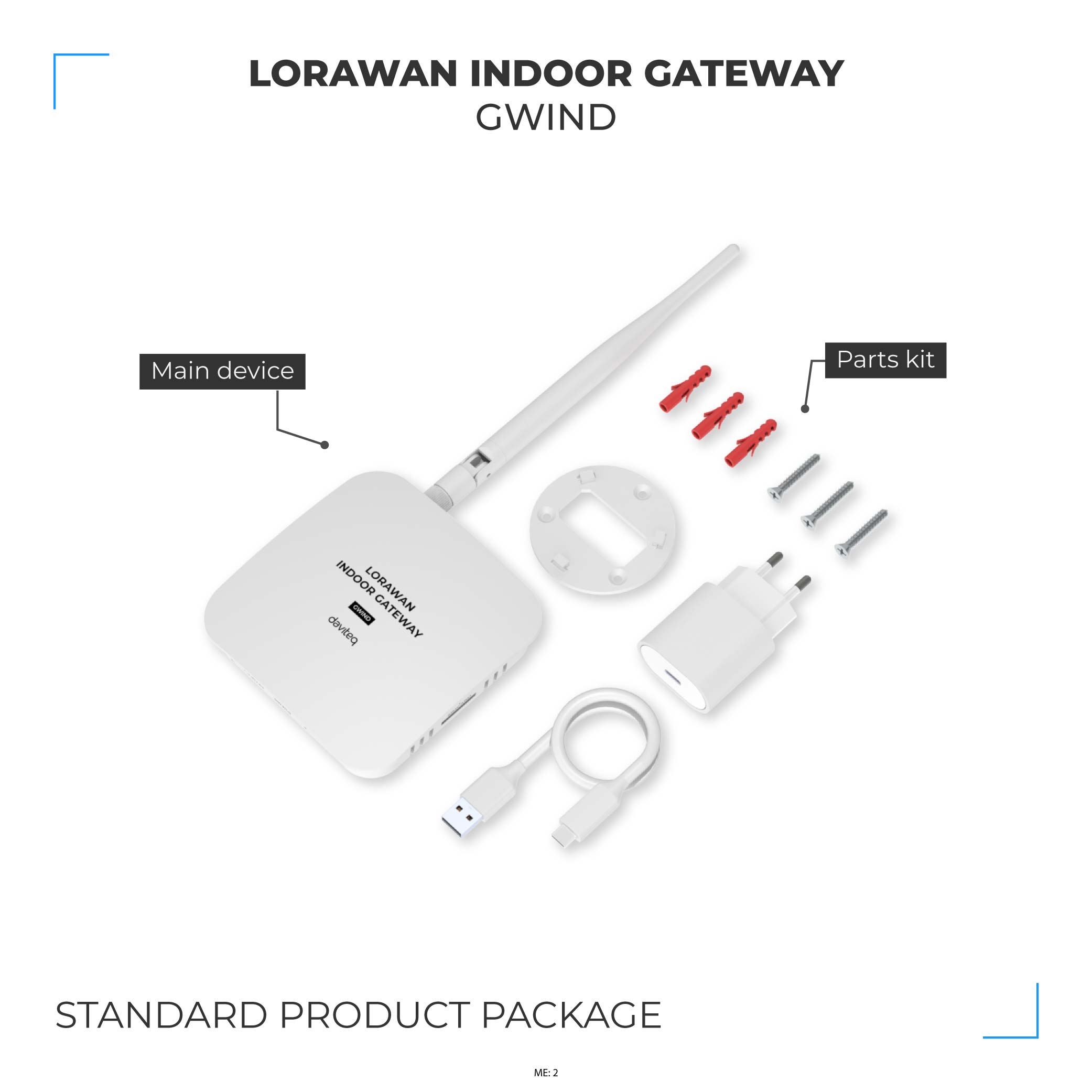
The package includes:
01 x LoraWAN GWIND Gateway
01 x Lora Antenna
01 x Power Adapter
01 x Converter cable
01 x Mounting Accessories
1.5 Product Overview
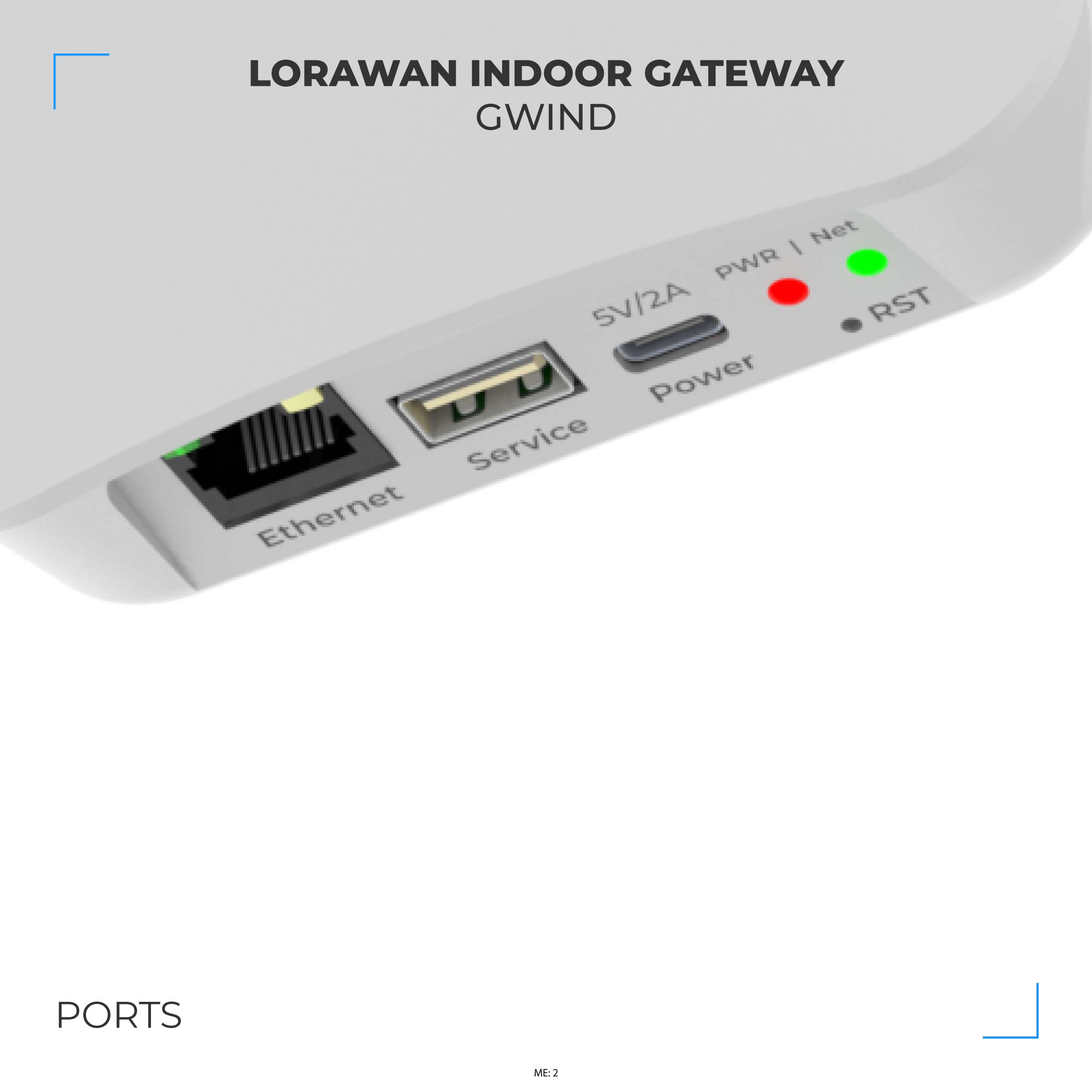
- LED Functions
| LED Functions | Constant | Flashing | Off |
| Power | Power On | None | OFF |
| Net | Connected | None | Disconnected |
Some configuration such as Packet Forwarder settings, VPN settings, WAN settings will be restored to factory defaults when reset process completely taken.
Use a pointed stick to poke the button inside the hole and hold for 5 seconds. The gateway will automatically perform reset process. The whole process will take a few minutes.
Reset the device only when absolutely necessary
1.6 Power Supply
- Power the LoRaWAN GWIND Gateway through the USB-Type C port, use 220 VAC to 5 VDC USB power adapter
1.7 Guide for Quick Test
Startup the LoraWAN Gateway through the following steps
Step 1: Install the antenna of the LoRaWAN Gateway
Install the Lora antenna in the correct position. Make sure the antenna and Gateway are tightly connected.
Step 2: Connect the Ethernet cable to the Gateway
Connect the Ethernet cable into Ethernet port.
Step 3: Insert the SIM card to SIM slot of the side of the gateway (optional), note the SIM direction as instruction label on the housing
Step 4 : Power up the Gateway through USB type C port using provided power adapter and USB cable
Step 5 : Access Gateway's GUI for configuration
There are two ways to access Gateway's GUI for configuration: via Wifi network or via Ethernet port
Access Gateway's GUI via Ethernet port
By default, the gateway is configured to use DHCP. Therefore, it must be connected to a network with an active DHCP server in order to access the Web GUI.
If the gateway is to be used in a static IP network without DHCP, it must firstly be connected to another active DHCP server to access the configuration interface to configure static IP for the gateway. Once the initial configuration is complete, the gateway can then be moved to the static IP network. Details of static IP configuration for the gateway are in sub-section of WAN SETTINGS in section of 2.2.6.2 Network WAN configuration
In some company with strict IT regulations, the gateway MAC address must be added to company network white list for proper connection.
- Use a computer to connect to the network that the gateway is connected. The computer can connect to that network via Ethernet.
- Use the IP scanning software to find the IP address of the gateway based on its Mac address that can be found on the back label.
Access this link to get a free IP scanning software on the internet
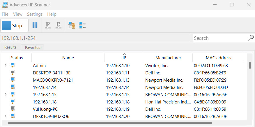
- Enter the IP address of the gateway in the web browser to access the configuration interface.
Must add port 4050 after the IP address. For example, If the IP address of the Gateway is 192.168.1.21 , you have to enter 192.168.1.21:4050 in web browser, then the GUI will be displayed.
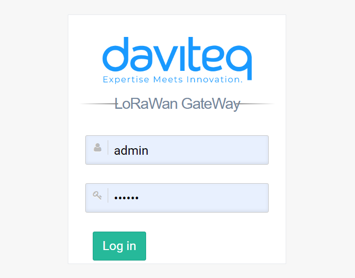
The default username is admin and default password is public. Please check updated username and password on the gateway label.
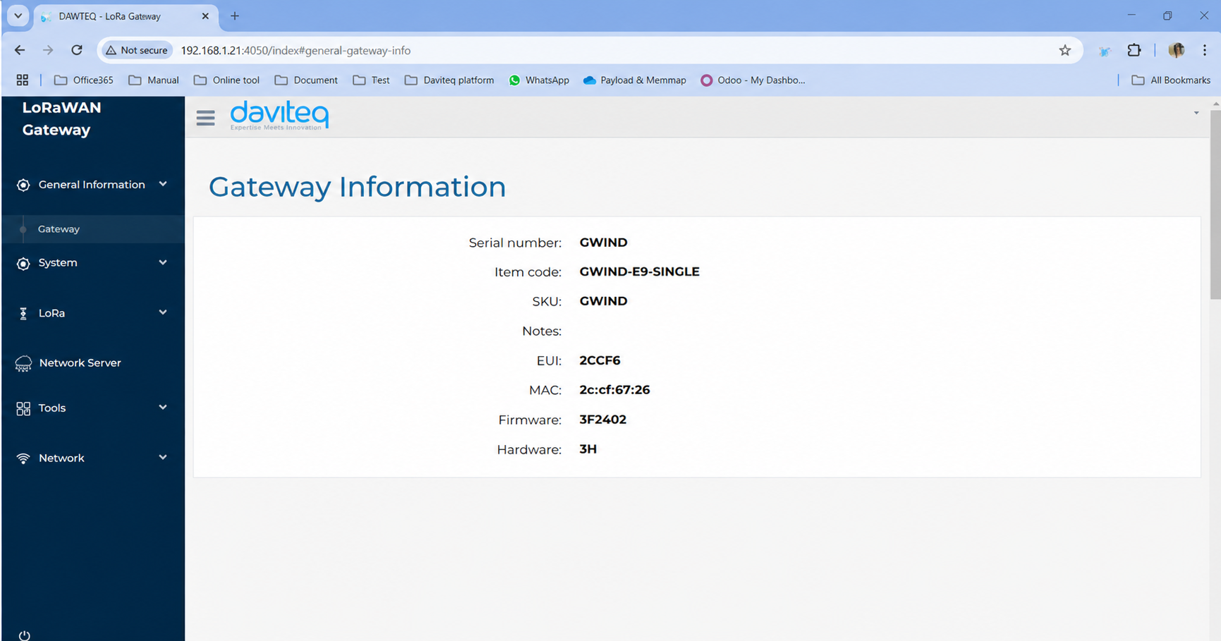
After login successfully, the general information of the gateway will be display at general information tab.
Access Gateway's GUI via gateway Wifi network
The gateway Wifi access point will be off automatically when user's PC has disconnect from this Wifi network
Step 6: Lora Settings
Package Forwarder
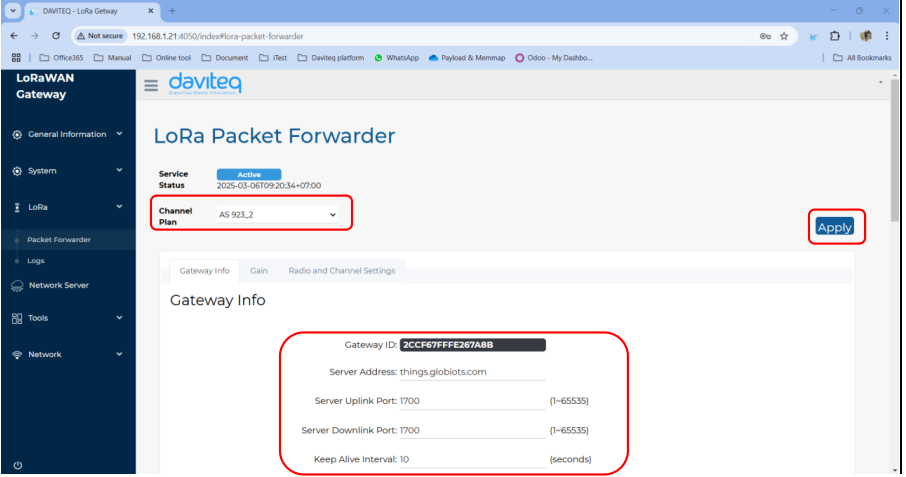
Select Packet Forwarder in the left menu, then choose Gateway Info. This page is for setting up the LoRa configuration including Channel Plan, Gateway ID, Server Address, Server Uplink Port, Server Downlink Port, Keep-Alive Interval, Statistics Display Interval, and Push Timeout
Need to properly configure the Server Address, Server Uplink Port, and Server Downlink Port fields. These information depend on the Network server.
Choose the channel plan for the gateway, then choose the Apply button at the bottom right to save the current configuration.
| Parameter name | Description | Default value |
| Channel Plan | The region refers to the specific geographical area where the gateway operates, following the LoRaWAN Regional Parameters defined by the LoRa Alliance | EU868 |
| Gateway ID | The Gateway ID (also known as DevEUI) is a unique identifier assigned to a LoRaWAN gateway. | Unique value |
| Server Address | The server address in a LoRaWAN gateway refers to the network server’s IP address or domain name that the gateway connects to for data transmission and management | localhost |
| Server Uplink Port | The server uplink port in a LoRaWAN gateway refers to the port number used to send uplink packets | 1680 |
| Server Downlink Port | The server downlink port in a LoRaWAN gateway is the port number used for receiving downlink packets | 1680 |
| Keep alive interval | The keep-alive interval is the time interval at which a LoRaWAN gateway sends periodic status messages (heartbeats) to the network server to indicate that it is active and connected. | 30 |
Watcher
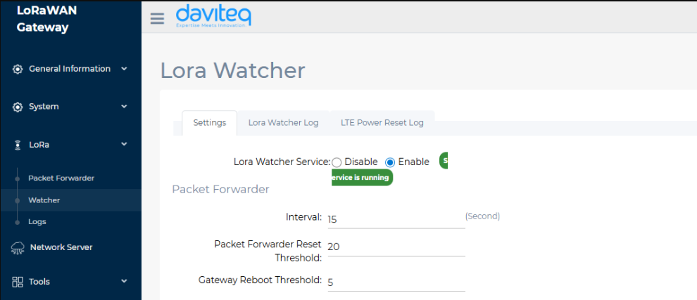
- Packet Forwarder:
- Interval: Interval for checking the system log to verify successful uplink to the network server.
- Packet Forwarder Reset Threshold: Number of consecutive uplink failures before resetting the packet forwarder
- Gateway Reboot Threshold: Number of packet forwarder resets before resetting the gateway.
Step 7: Network WAN configuration
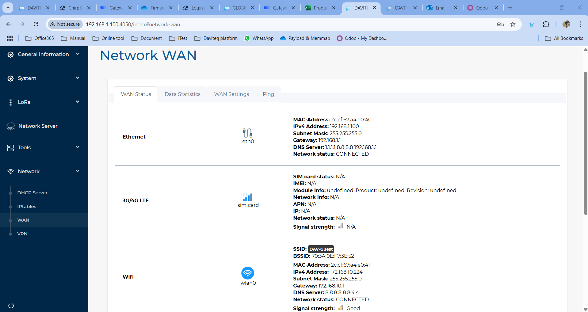
This category shows current WAN settings. This category is further divided into three sectors: WAN Status, Data Statistics and WAN Settings.
-
WAN Status
The current network status will be shown on this page.
-
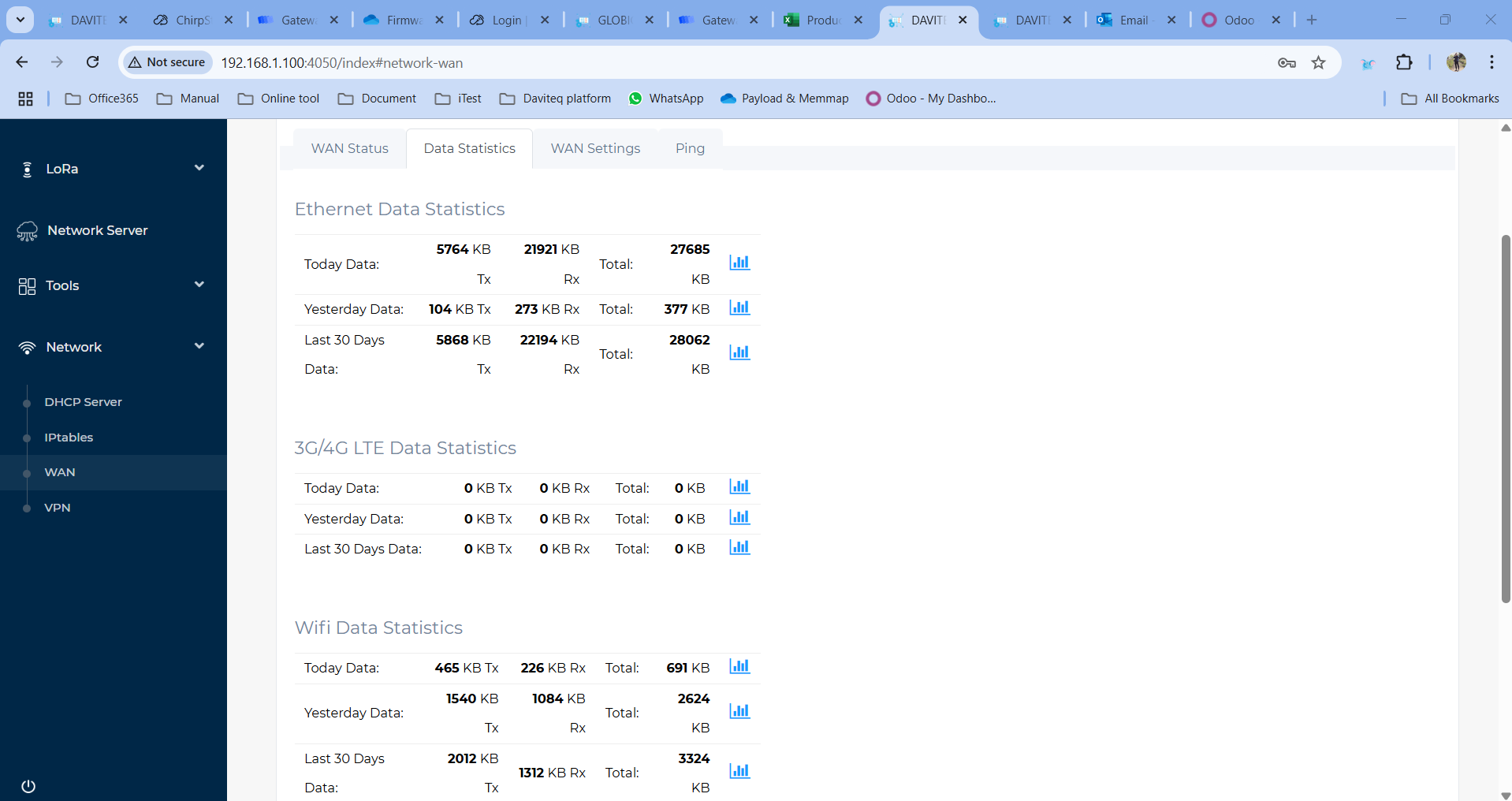
WAN Statistics
Statistics on the gateway's used data capacity are shown in this section
-
WAN Settings
Daviteq Gateway supports internet connectivity via both Ethernet , Wi-Fi (optional) or Cellular (optional).
The default Ethernet mode is DHCP.
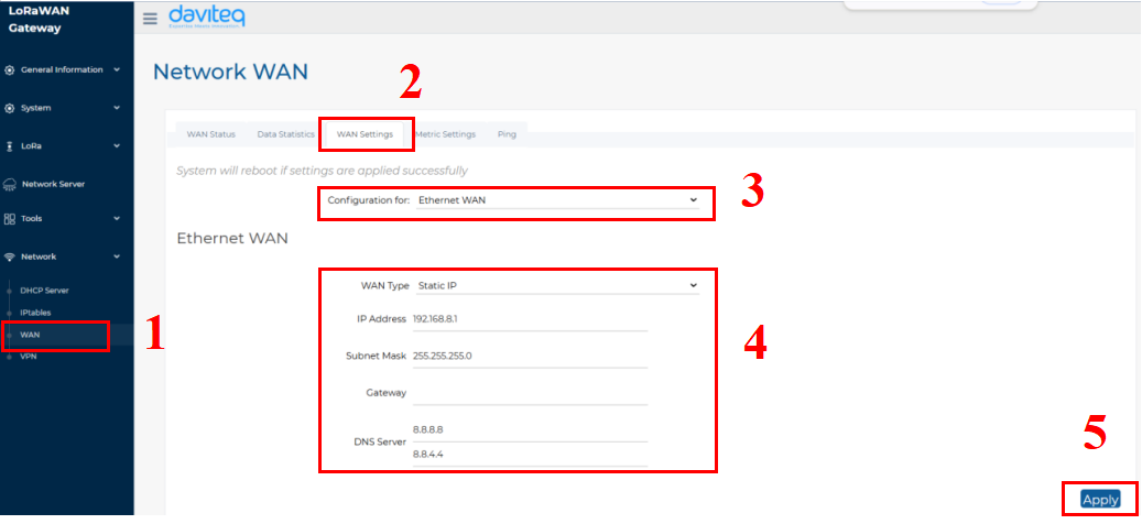
- Follow the steps below to set up the Ethernet network to static mode.
Step 1: In the Network section, select WAN.
Step 2: Click on the WAN Settings tab at the top.
Step 3: In the Configuration field, select Ethernet WAN
Step 4: Enter the Ethernet WAN information, including WAN Type, IP address, Subnet Mask, Gateway and DNS server
Step 5: Click the Apply button to save and apply the new configuration.
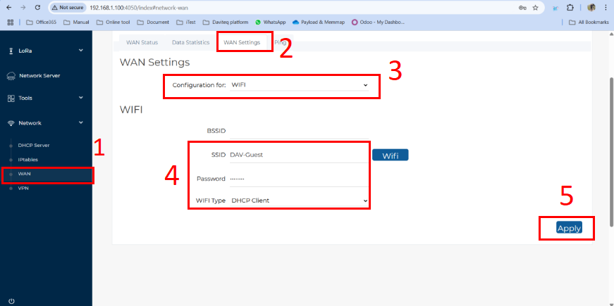
- Follow the steps below to set up the Wi-Fi network for the gateway:
Step 1: In the Network section, select WAN.
Step 2: Click on the WAN Settings tab at the top.
Step 3: In the Configuration field, select Wi-Fi.
Step 4: Enter the Wi-Fi information, including SSID (Wi-Fi name), Password, and Wi-Fi Type (default: DHCP Client).
Step 5: Click the Apply button to save and apply the new configuration.
- Follow the steps below to set up the Cellular network for the gateway:
Step 1: In the Network section, select WAN.
Step 2: Click on the WAN Settings tab at the top.
Step 3: In the Configuration field, select 3G/4G LTE
Step 4: Enter the 3G/4G LTE information, including APN, Username, Password, and Authentication Method (base on the SIM card provider).
Step 5: Click the Apply button to save and apply the new configuration.
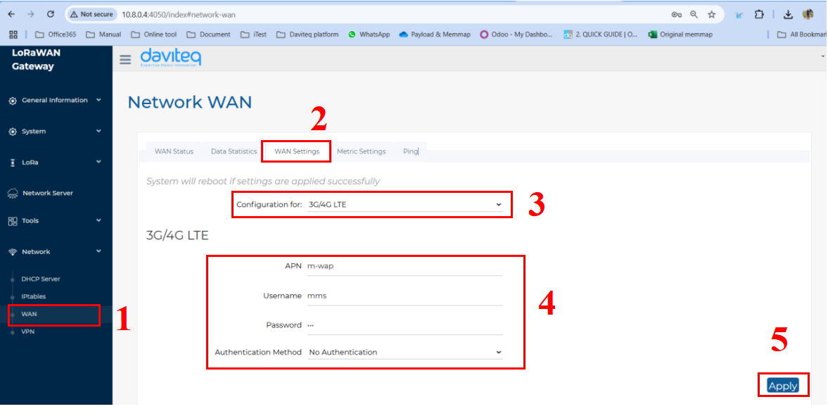
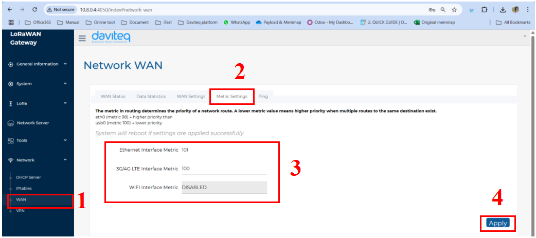
- Follow the steps below to set up network priority
The metric in routing determines the priority of a network route. A lower metric value means higher priority when multiple routes to the same destination exist. For example, 100 is higher priority than 101.
Step 1: In the Network section, select WAN.
Step 2: Click on the Metric settings tab at the top.
Step 3: Enter the the metric factor for available network.
Step 4: Click the Apply button to save and apply the new configuration.
1.8 Gateway Communication
1.8.1 Gateway communication to LoRaWAN device
1.8.2 Gateway communication to Network Server
1.8.2.1 Add the LoraWAN Gateway to Embedded Chirp Stack Network Server
Please follow instruction at link:
Instruction to configu... | Online Product Manuals & Datasheets
1.8.2.2 Add the LoraWAN Gateway to External LoRaWAN Network Server
To give an example, please follow the instructions in this link to add LoraWAN gateway to The things Stack network server
1.8.3 Activate and configure the embedded Node RED development tool
Prerequisite:
The Embedded Chirp Stack Network Server in the gateway must be active and configured properly to forward data to embedded Node RED development tool. Details to activate and configure embedded Chirp Stack are at the link: https://daviteq.com/en/manuals/books/manual-for-lorawan-sensor/page/instruction-to-configure-embedded-chirpstack-network-server-in-the-gateway
Please refer the below link for instruction to add the embedded Node RED development tool:
Instructions to config... | Online Product Manuals & Datasheets
To give an example, please follow the instructions in this link to add LoraWAN gateway to The things Stack network server
1.9 Default Configuration
| Configuration | Default value |
| Time zone | UTC |
| LoRaWAN Frequency plan | EU868 |
| Network Server host | localhost |
| NS uplink port | 1700 |
| NS downlink port | 1700 |
| Network Server Settings description | OFF |
| NS integration descriptions | OFF |
| NodeRED Settings descriptions | OFF |
| IP forwarding | OFF |
| WAN Ethernet Settings | DHCP Client |
| VPN setting | OFF |
| Ethernet Interface Metric | 100 |
| 3G/4G LTE Interface Metric | 101 |
| WIFI Interface Metric | DISABLED |
| Lora Watcher Service | ENABLE |
| Packet Forwarder Interval | 15 |
| Packet Forwarder Reset Threshold | 20 |
| Gateway Reboot Threshold | 5 |
1.10 Installation and Wiring
-
Mounting Location Requirements
-
- Mount about 3 m above the ground and about 1 m below the ceiling for the best LoRaWAN signal transmission
-
- Mount well away from the ground, the ceiling surface and any metal/glass objects.
-
- Mount on an open pole or on a wall, ensuring the RF path from the gateway antenna to the LoRaWAN nodes is obstructed as little as possible (apple-shaped beam centered on the antenna tip).
- The RF path to the nodes should avoid metal and glass obstructions.
-
Mechanical Installation Steps
- Step 1: Screw the supplied antenna onto the gateway.
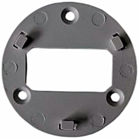
- Step 2: Mount the gateway base onto the pole/wall using 3 provided screws to fix into the 3 holes on the base. Note the horizontal/vertical orientation of the base exactly as shown so the gateway stands upright with the antenna pointing up.
-
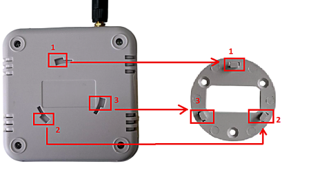
- Step 3: Place the gateway onto the base so that the 3 holes on the gateway's back align with the 3 tabs/ridges on the base.
-
- Step 4 : Turn the gateway gently clockwise to lock it onto the base.
No Comments